Sailing Vessel (SV) Sarah
Sarah has a new owner as of 7/26/2021. There will be no more updates to these SV Sarah pages
Sarah has a new owner as of 7/26/2021. There will be no more updates to these SV Sarah pages
| Deck and Rigging Upgrades | |
| Over the winter of 2003 I removed both the main and mizzen masts for a complete overhaul of Sarah's running rigging. Those upgrades are described on the 2003 Rigging Upgrade page. This page documents all other changes to Sarah's rigging and deck equipment. | |
|
Contents: |
|
| Ground Tackle | |
|
In
2001 I added a 44# Bruce to the existing 44# Chinese CQR
anchor. At the same time I added a separate rode for the Bruce consisting of 50' 3/8"
proof coil chain and
400' of 3/4" rope. This required a change in the chain
wheel on
the Lofrans windlass. In 2009 both of these anchors were replaced by a Manson Supreme 60. I retained the Bruce as my backup anchor for several years, but it no longer sat in a roller on the bow. In 2012 I sold the Bruce and replaced it with a Fortress Anchor. Sarah came with Lofrans Royal manual windlass, which I replaced with a Quick Hector electric windlass in 2013. I have created a separate page on the installation of that windlass. |
 44# Bruce in Anchor Roller |
| All Chain Rode, 2008 | |
 Painting Length Markers |
After
7 years of using the 50' of 3/8" chain and 400' of rope rode I was ready to go to an
all-chain-rode. I was initially concerned that if the windlass failed
I would not be able to bring an all chain rode aboard by hand. What I
failed to realize that if I'm anchored in less than 50' of water the weight
of the all chain rode is the same as my 50' of chain. Actually if I
went to 5/16" chain the all chain rode would weigh considerably less than my
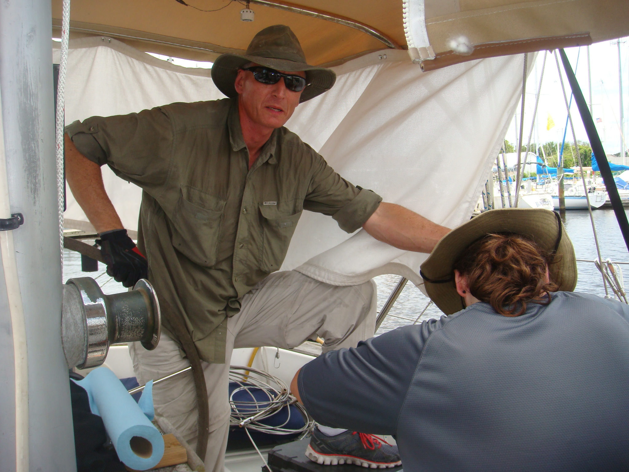
3/8" chain rode. So finally in August, 2008 I ordered a half-pail (275') of 5/16" G40 chain from 1st-ChainSupply.com. Of course this required another chain wheel for the Lofrans Windlass. When the chain finally arrived I (with help from Tom Widmer) dragged it down the dock and flaked it so that I could apply paint to mark the chain length. In the picture on the left I have started the painting of length markers using Rust-Oleum. |
| I used both drop clothes and plastic paint liners to keep the paint on the chain and not on the dock. |
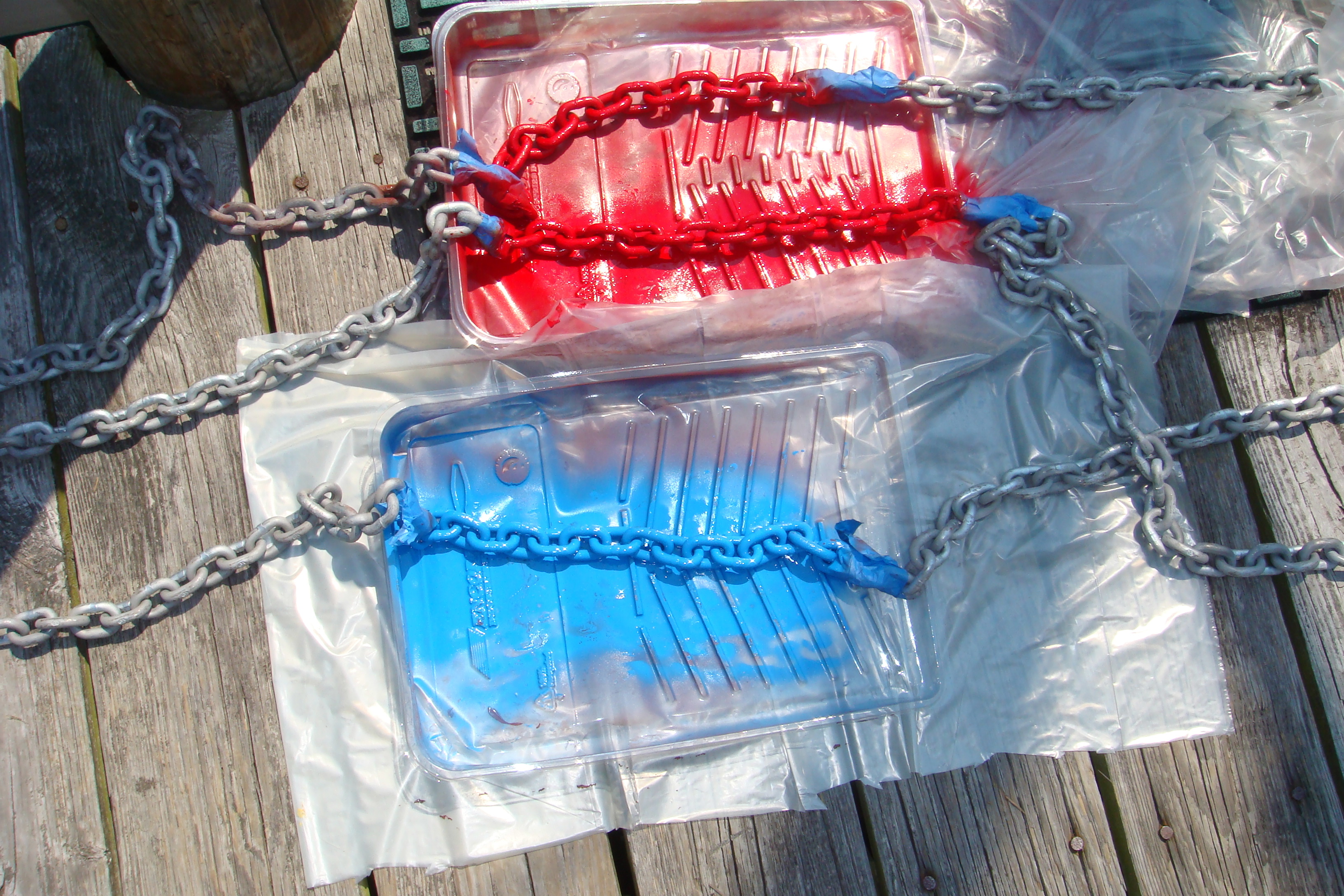 Protecting the Dock During Painting |
 125' Marker |
This long red marker indicates 125' of chain. |
|
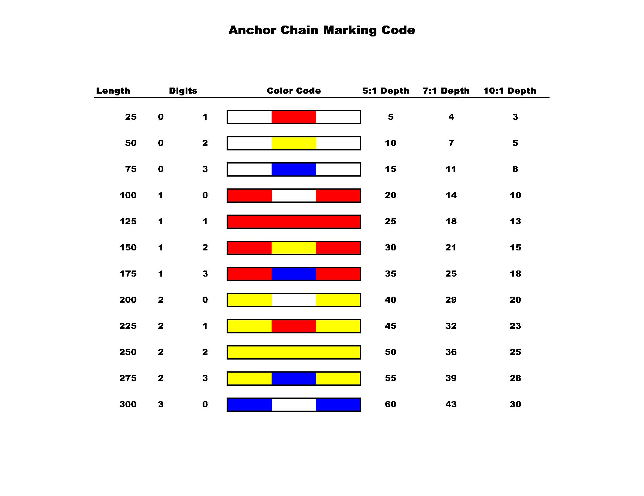
On the right are the color-coded depth markers for the anchor chain. I got
this scheme from the
Yandina
website. At first it seemed a little difficult to use, but after
studying it for a bit I recognized that it could be very effective. Bare
Chain =0 |
 Yandina Anchor Marking Scheme |
|
White in the diagram represents bare chain. Each of the colors then is a multiplier of either 25' or 100' depending on whether the color is in the center of the marker or on the outside. The center colors are multipliers of 25' and the outer markers are multipliers of 100'. I think the strength of the scheme is that it is symmetrical, you can read it easily from either direction, and it should be readable even if the marker is under several feet of water. The big issue will be how well the paint holds after several times through the windlass chain wheel and after dragging through sand. I used Rust-Oleum paint and primer on the chain. Turns out maybe I should have used the primer intended for galvanized metal. What I used was probably formulated for aluminum. It didn't take many runs through the windlass or days buried in Bahamas sand for the marking paint to disappear. For the markings below 100' I now have only the faintest of colors. In 2010 I replaced the painted markers with collored cable-ties. I continued the same color scheme using 6 cable-ties in separate chain links for the markers. I expect the cable-ties will not last any longer than the paint, but they are a lot easier to restore. I still need to drop the first 50' of the chain on the dock and measure off the 25' and 50' lengths. When storms were coming through the Abacos in the winter of 2008-2009 I usually let out about 125' of chain. That meant at least the first 50' was buried in the sand. After that winter there is not a trace of the paint markers for the 25' and 50' lengths. In 2013 I installed a Quick Hector electric windlass, which included a remote control with a chain counter. Now I use the chain counter to determine how much rode has been deployed and no longer use chain markings. |
|
| Manson Supreme Anchor, 2009 | |
| Over the winter of 2009 I dragged anchor twice using the Bruce. Once in Willoughby Bay and again in the Bells River. Both times were in gales and the anchor did reset each time, but I think the gods were telling me the Bruce might be a little undersized for this boat. My back up anchor, the Harborfast 45 had dragged several times in conditions much less than a gale. I had been following discussions of the newer anchor designs such as the Rocna and Manson Supreme. | |
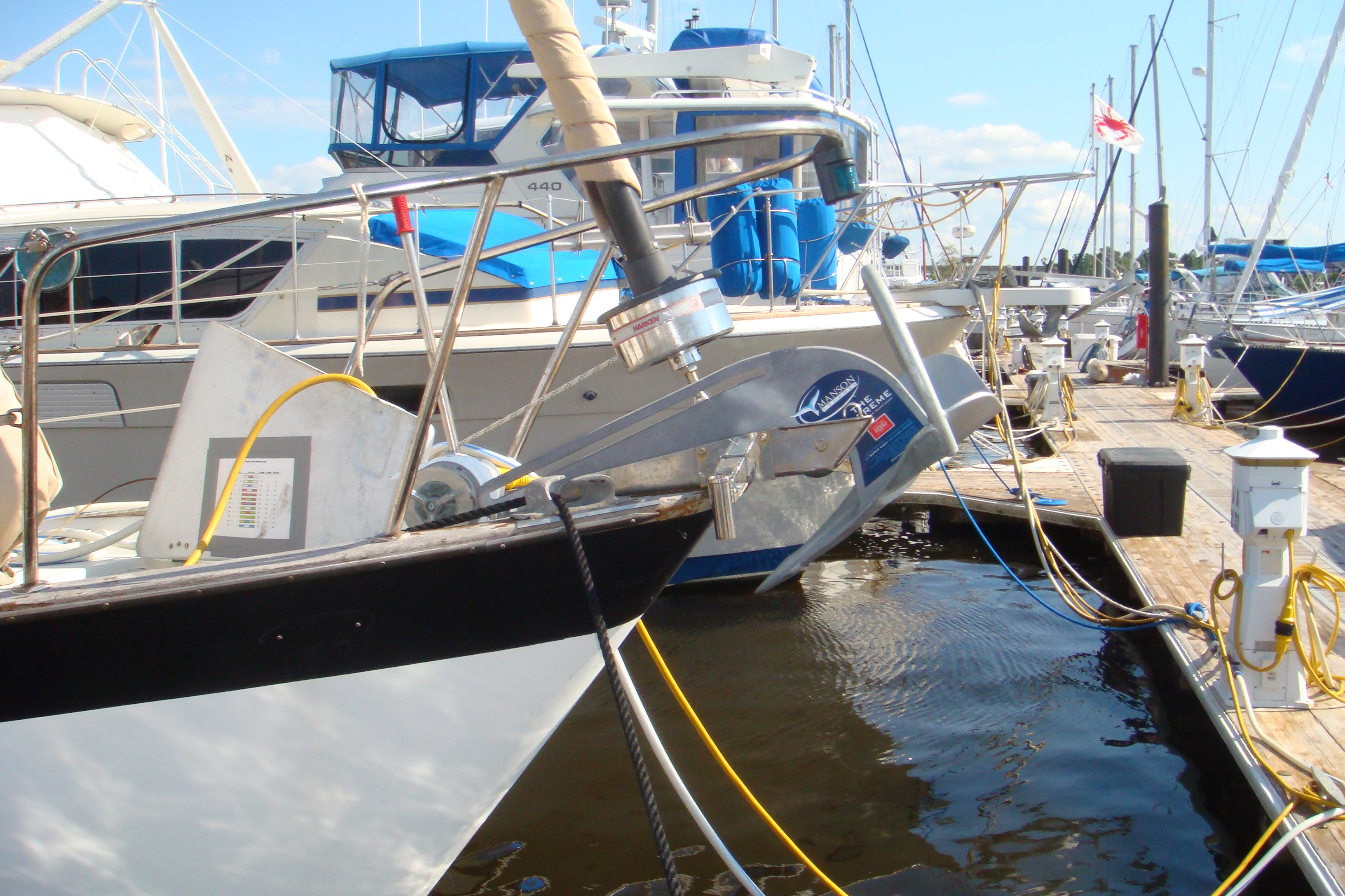
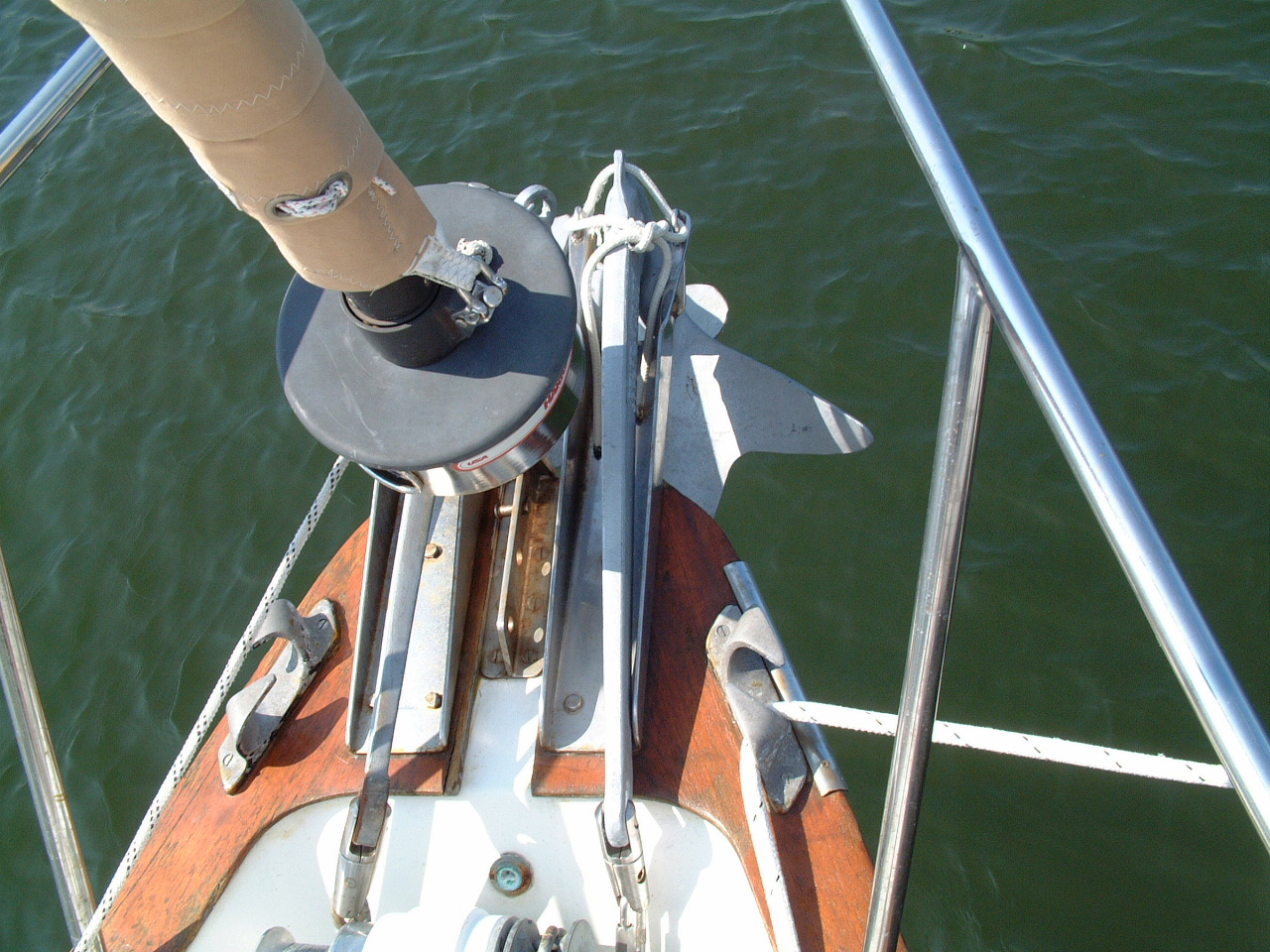
60# Manson in the Bow Roller |
I talked to several owners of these anchors while in the Bahamas that winter. Those owners were true believers in their anchors. Then Jack Tyler sent me some pictures of the Manson Supreme 60 he had mounted on Whoosh. Shortly after I berthed Sarah in New Bern, NC for the summer of 2009 I purchased a Manson Supreme. The picture on the left shows the anchor sitting comfortably in the starboard bow roller. |
| I will now carry just one anchor on the bow, so although the Manson is 15 lbs heavier than the other anchors it will provide a net reduction in weight on the bow of 30 lbs. |
 Only One Anchor on Sarah's Bow |
 Securing the Anchor Shank to the Deck |
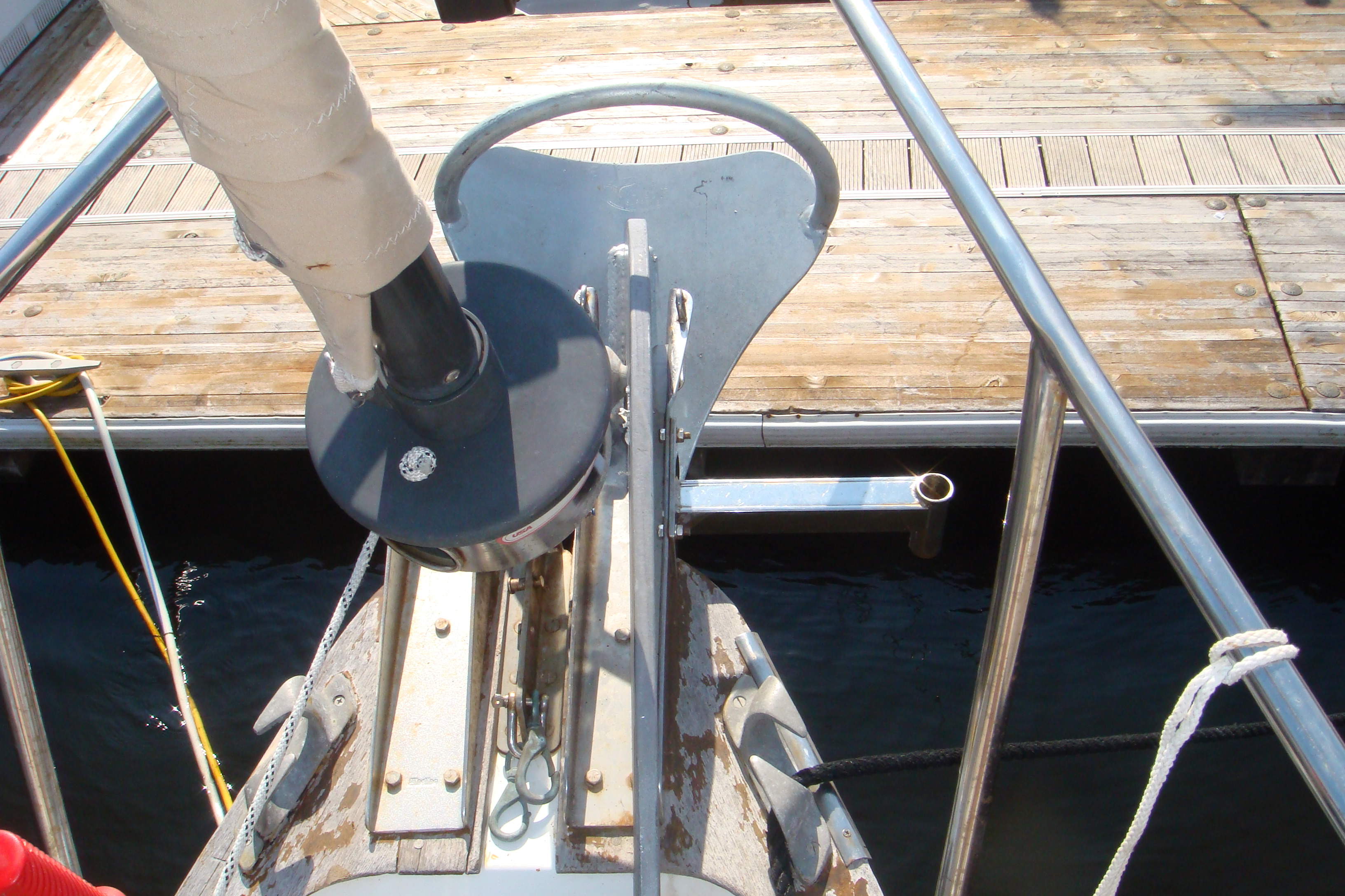
I
was fortunate that the snap shackle I used to secure the shank of the Bruce
Anchor will work for the Manson. I expected to have to move it. That heavily corroded bow shackle in the picture on the left is what happens when you spend 4 consecutive months at anchor. I still need to work out a better deck pipe arrangement for the chain. The current deck pipe cannot be sealed with chain on deck. So I need to disconnect the chain from the anchor if I'm going to be sailing in rough seas. |
| That anchor sorta dominates the bow, doesn't it? |
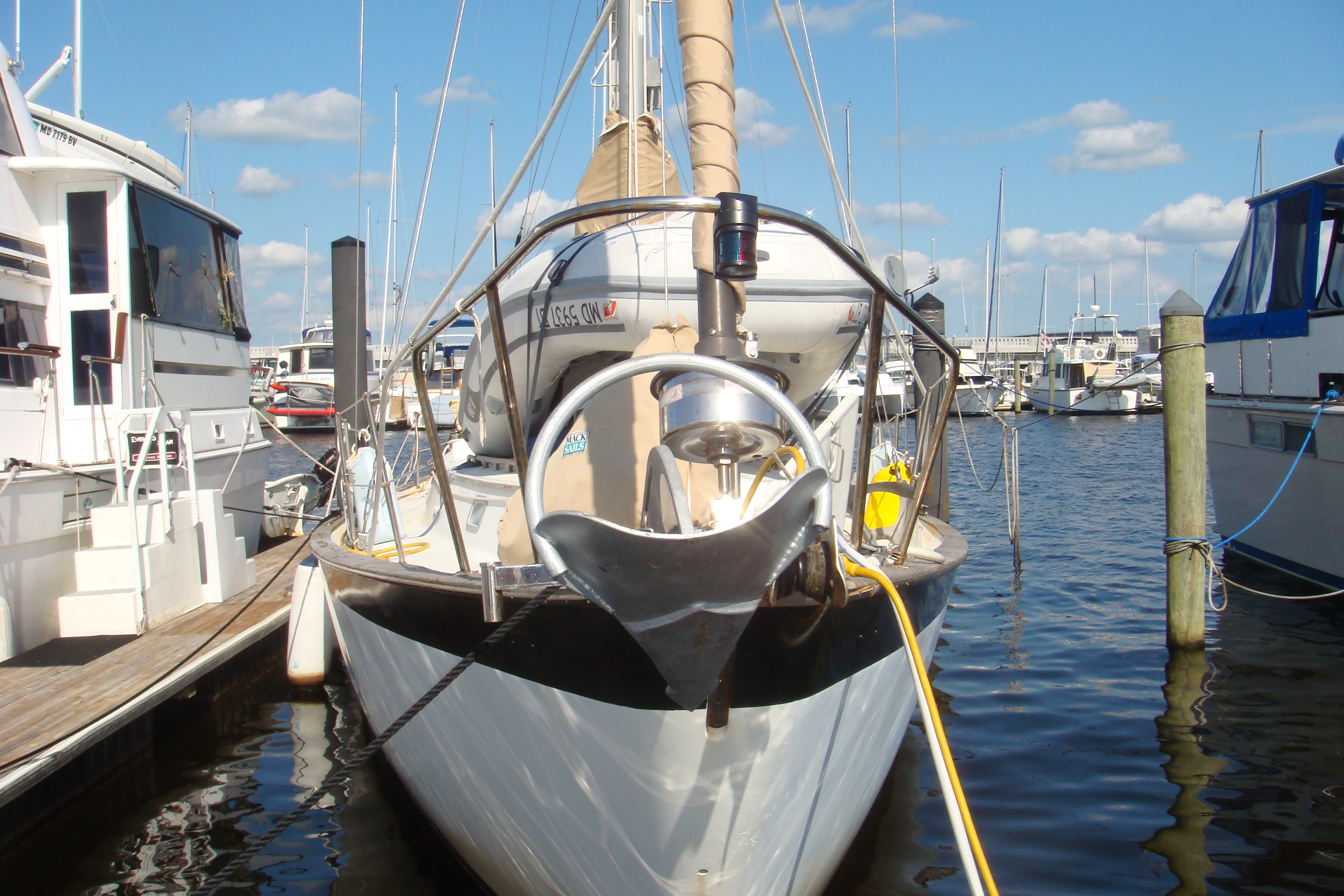 View of the Bow |
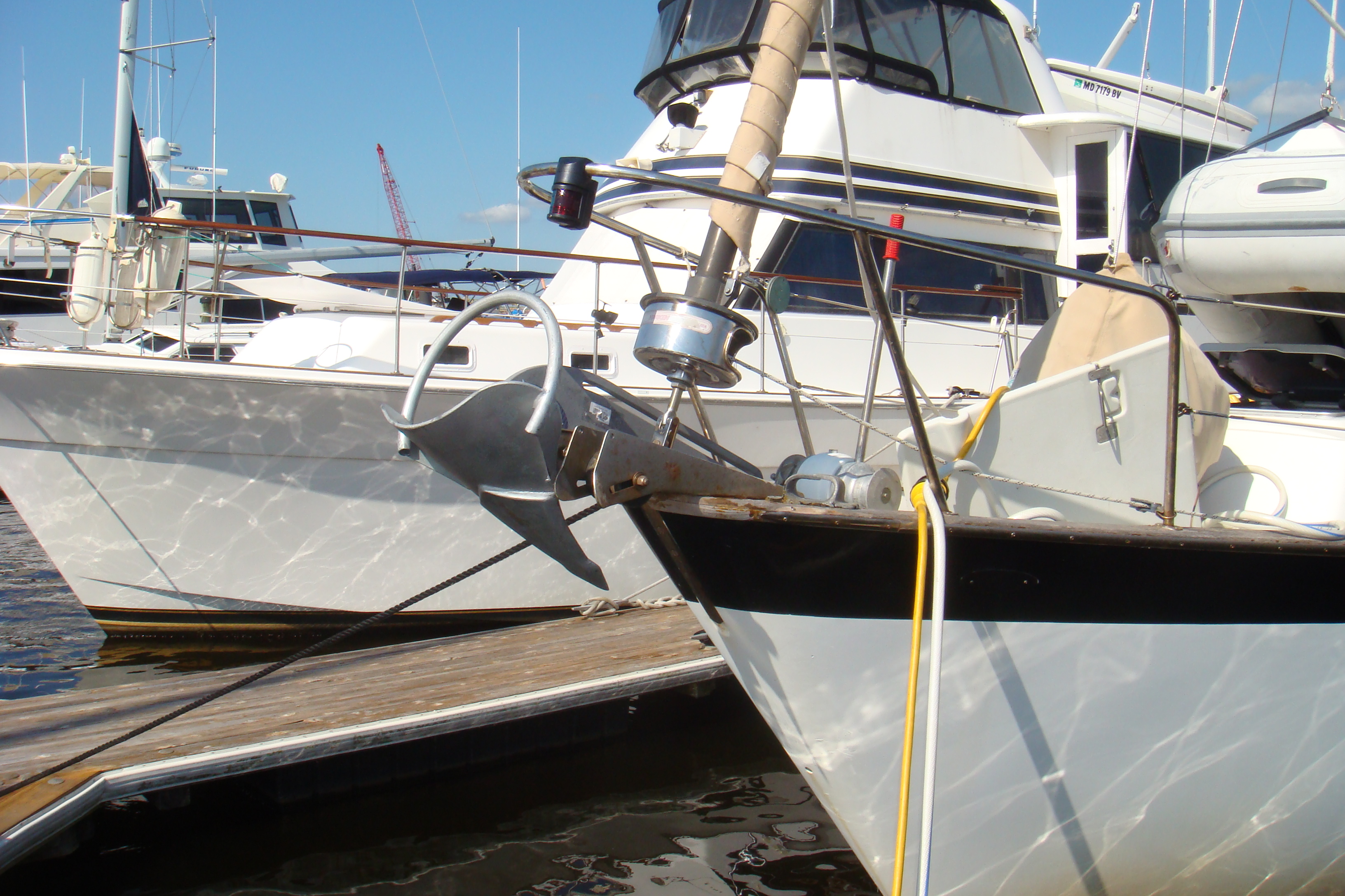 View From the Port Side |
I'm still working out the tie-down
arrangement for this anchor. The snap shackle should keep the anchor
on deck, but I needed to tie-down the crown of the anchor so it doesn't
bounce out of the roller when underway. For several years I used 3/16" cordage to tie down the the crown of the anchor. That solution failed on night just off shore when the cordage chafed through and the anchor came loose. Eventually I replaced the anchor roller with one with a bale that kept the anchor in the roller. |
| I kept the Bruce anchor for several years as my backup anchor. It was stored in the port lazarette locker. I never had to use it, but it was clear that hauling that anchor out of the locker and down the deck would not be fun. In 2012 I sold the Bruce on eBay and purchased a Fortress FX-23. this anchor is not only very light (15 lbs), but also can be dis-assembled for storage (see picture on the right). I still have a 12 lb Danforth, that came with the boat, on the stern rail. |
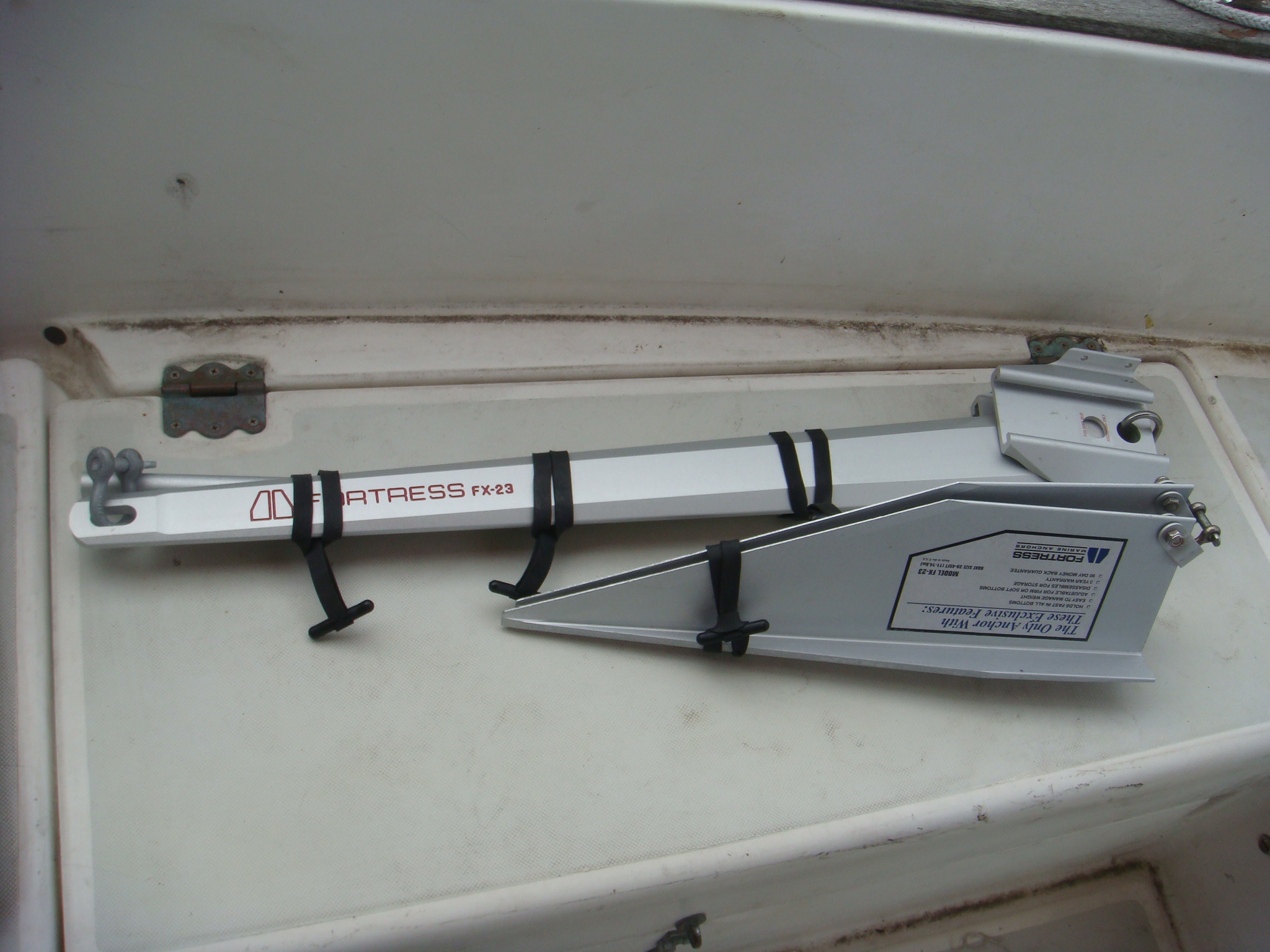 Fortress FX-23 Dis-Assembled |
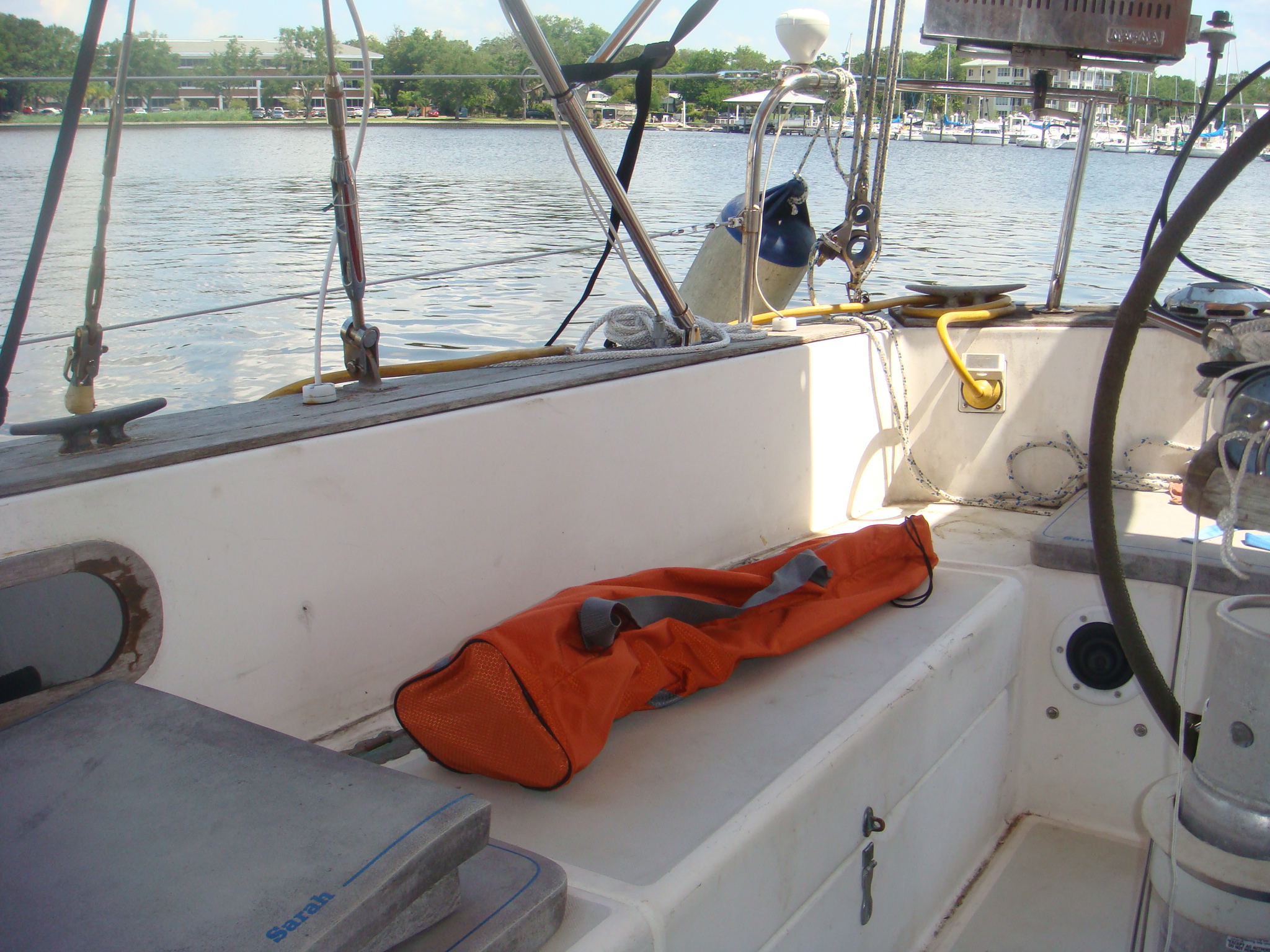 Storage Sack for the FX-23 |
And the anchor fits neatly in a storage sack as shown on the left. This sack came with a folding deck chair, but it is much more useful for anchor storage. |
| Anchor Well Modifications, 2010 | |
|
When I purchased Sarah all of the ground tackle was stored in the anchor
well in the foredeck. This did not allow for more than a min imal
amount of chain and rode (< 200'). That was marginally acceptable on
the Chesapeake Bay where typical anchorages are 10' or less in depth.
However for cruising I knew I would need much more chain and rope.
There is a chain locker beneath the anchor well, forward of the v-berth in
the forward cabin, but there was no access to that locker from the anchor
well. There is a deck pipe next to the anchor well that does provide
access to the locker. This deck pipe was intended for a cowl vent,
which was not included in the equipment that conveyed with the boat when I
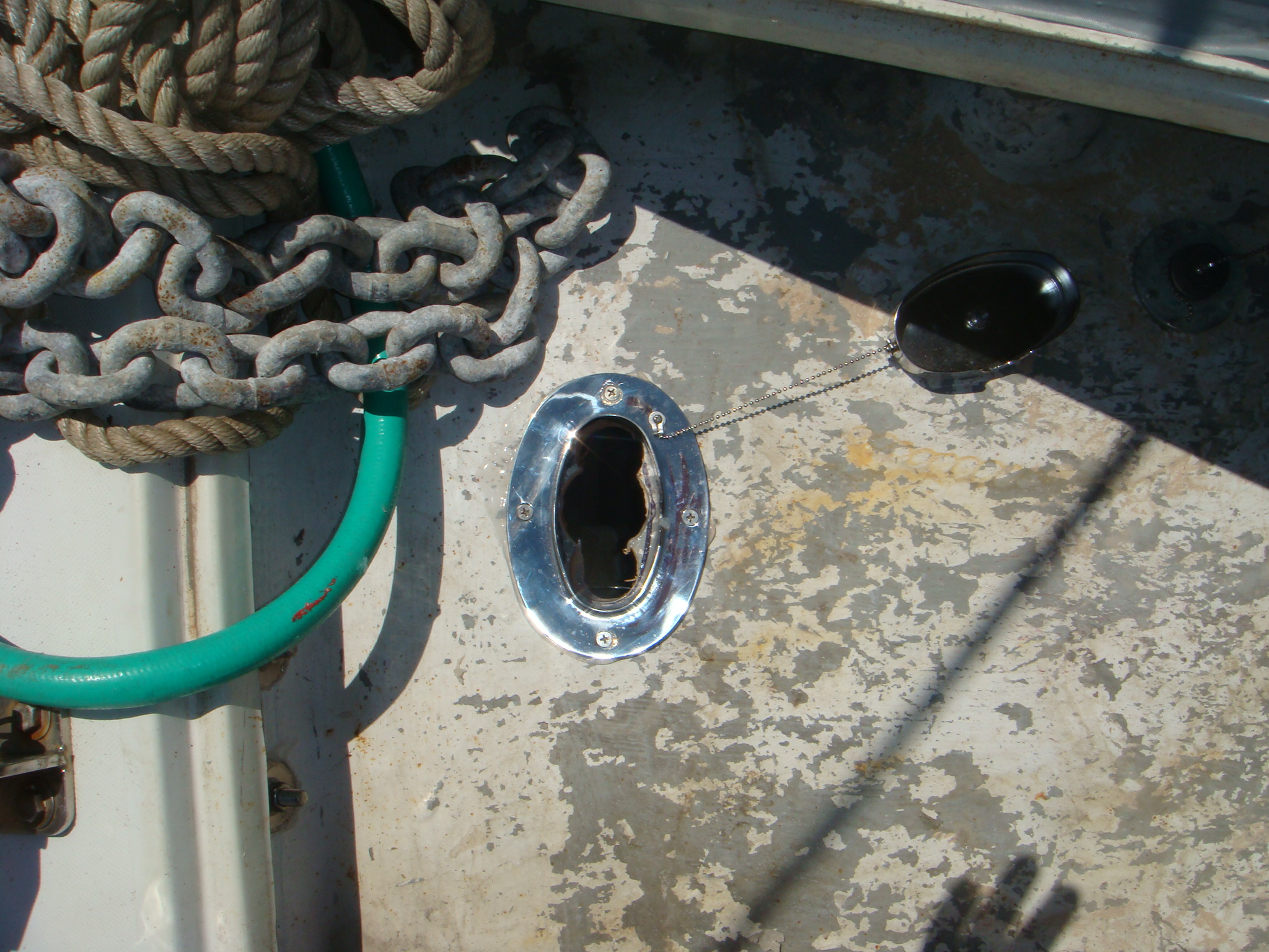
purchased it. So I used this deck pipe for the anchor rode. This was never a completely satisfactory arrangement as the deck pipe could not be closed off when the anchor rode was attached to the anchor. If it rained while I was anchored I had to throw a cushion or sail bag over the pipe to keep water from pouring into the chain locker. Also whenever I was sailing I had to disconnect the chain from the anchor and drop it down into the locker so I could seal off the pipe. |
|
 Hole Cut for Deck Plate |
Finally
in 2010 I decided cut a deck pipe into the locker from the bottom of the
anchor well. With this arrangement I could leave the chain attached to
the anchor for short passages. When anchored and it started raining I
only will have to close the lid on the anchor well. In the picture on the left I have cut the hole in the bottom of the anchor well using a couple of hole saws. I cut the two holes at the ends of the opening with a 1-1/2" hole saw and the center hole with a 2" hole saw. |
| Then I fitted the deck plate over the hole and sealed it. |
 Deck Plate Fitted in Anchor Well |
|
In addition to providing better access to the chain locker from deck, I also
needed to improve the hatch that provides access to the locker from the
forward cabin. This hatch is just a piece of 1/2" Teak veneer plywood
that covers the hole in the bulkhead between the foot of the berth and the
chain locker. As implemented by Pearson, this hatch was held in place by a
couple of wooden cleats at the bottom and at the top with a common friction
door holder. Clearly this hatch was not intended to secure the chain
locker for anything but an all-rope anchor rode with minimal chain.
Even before I went to all chain, the anchor rode would knock this hatch free
and allow the rode to spill onto the foot of the berth. I needed a way
to secure this hatch so that when the rode shifts around in the locker (e.g.
in rough weather) that the hatch stays in place. The simple solution
would be to just seal up this opening in the bulkhead. However it is
often necessary to have access to the locker from below to knock down chain
castles and rope piles to allow off the rode to fit into the locker. I had looked at a number of ways to secure this hatch, but all had serious shortcomings and probably would not have worked all that well. Then when I installed additional hatches in the cabin sole I realized the type of latch I was using to secure the cabin sole hatches would also work on the chain locker hatch. |
|
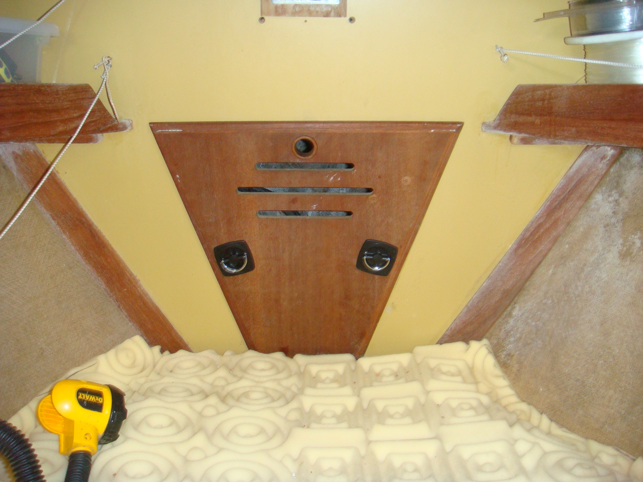 Chain Locker Hatch |
The picture on the left shows the hatch secured in places with a couple of Perko latches (Model Nr 0932). |
| This picture shows the backs of the latches. Similar to the ones I used on the cabin sole hatches, these latches have a cam bar that secures behind the bulkhead holding the hatch in place. |
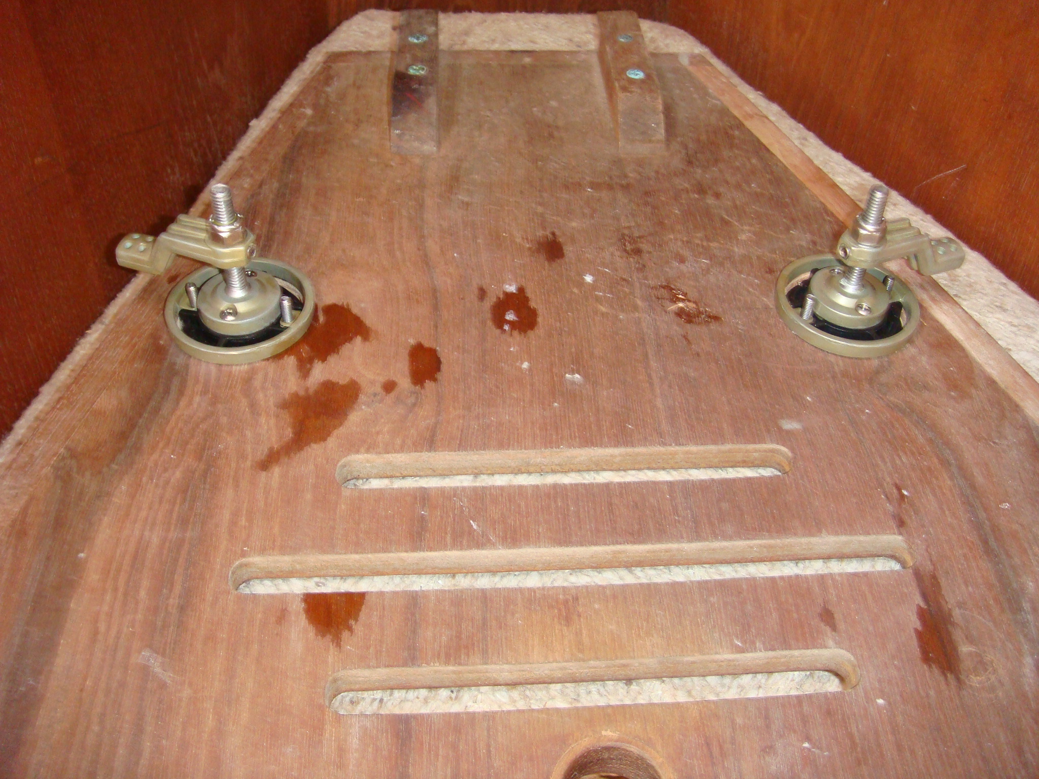 Latches on Chain Locker Hatch |
| Soft Shackles, 2013 | |
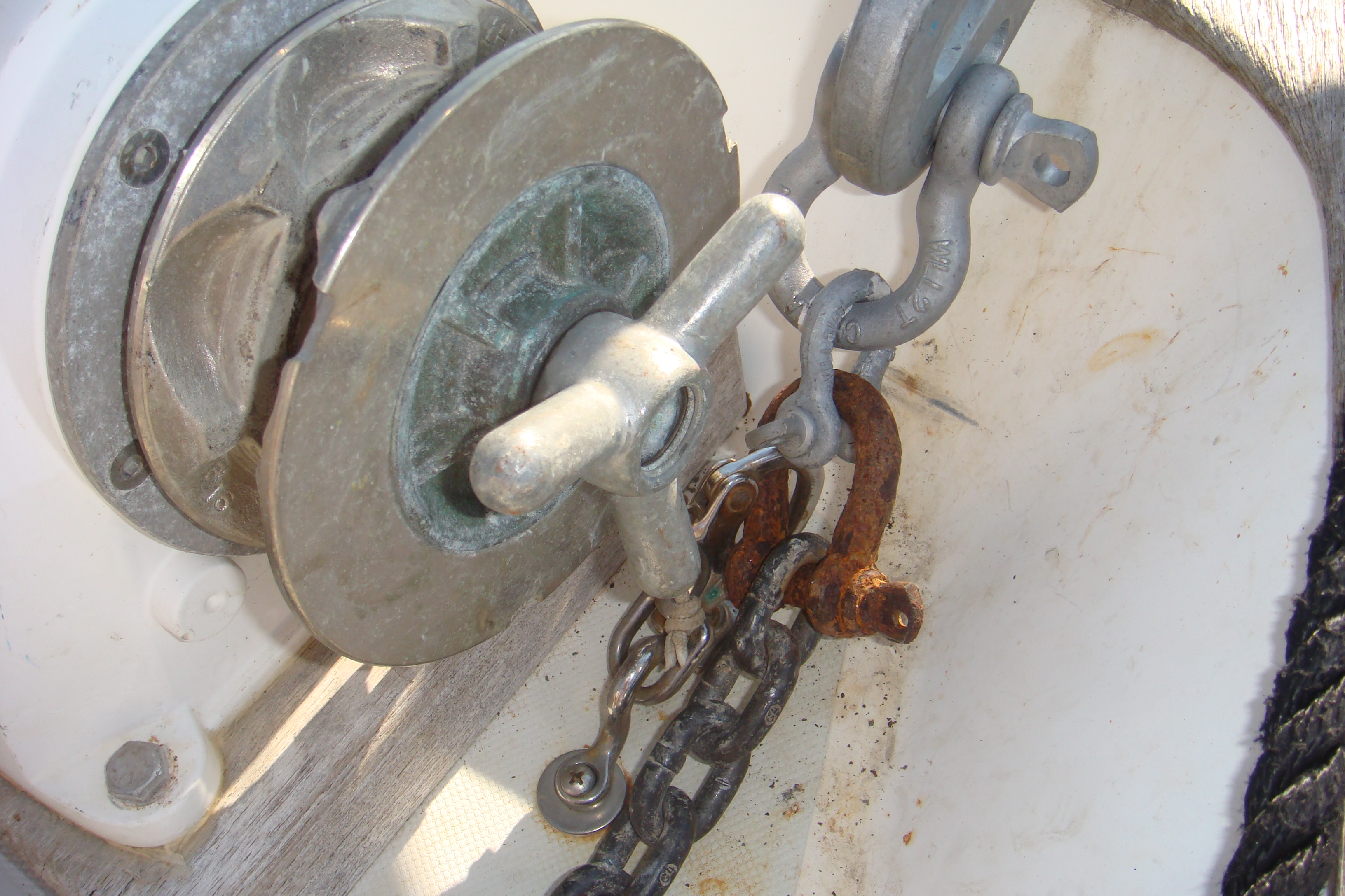
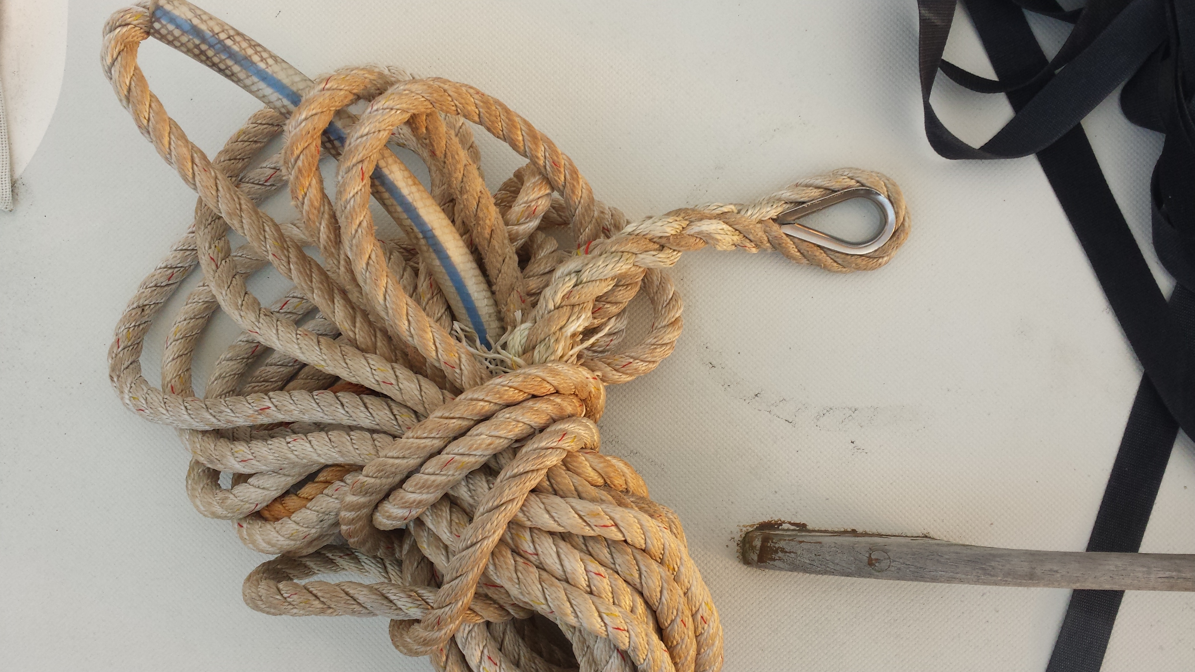
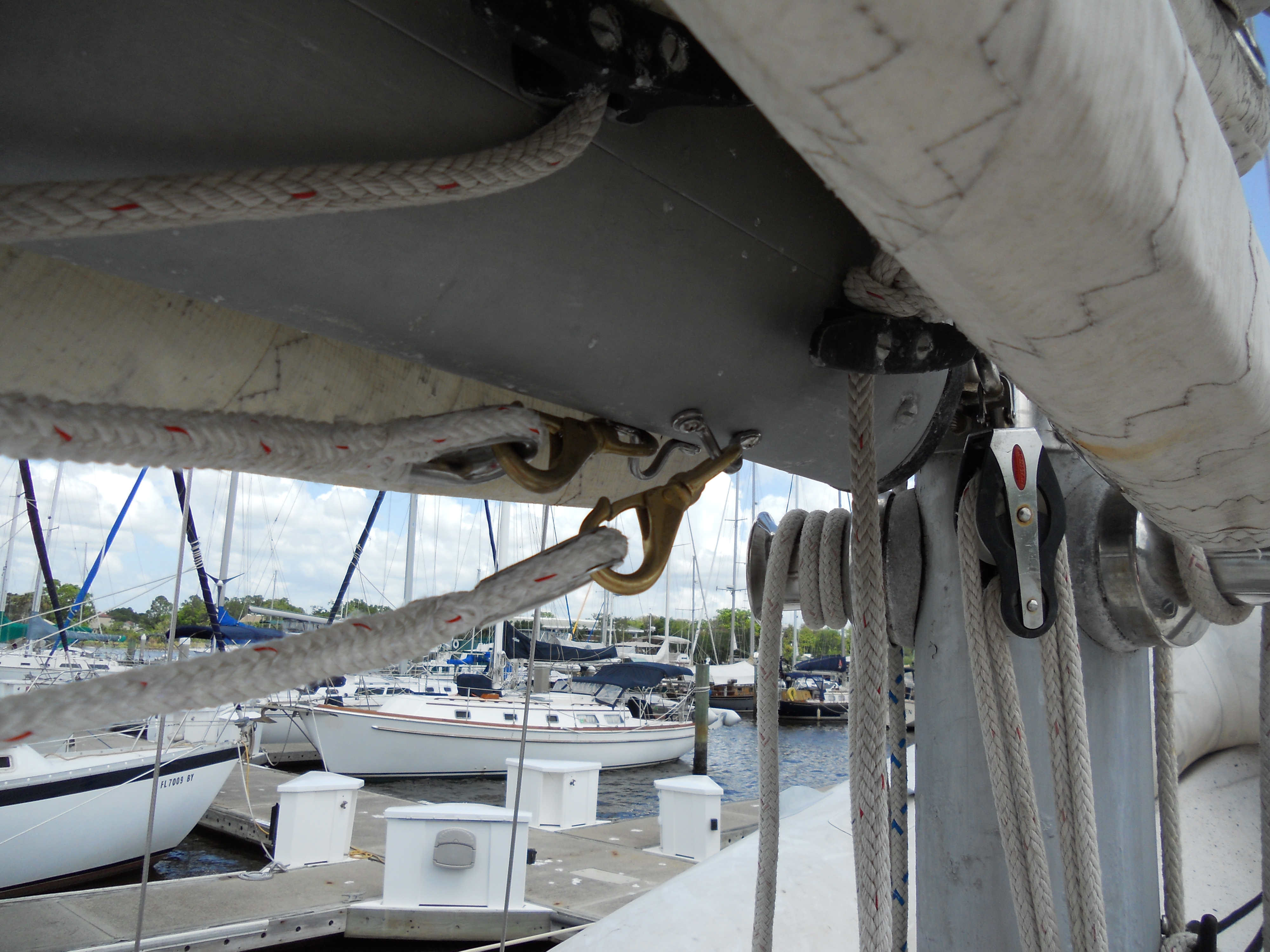
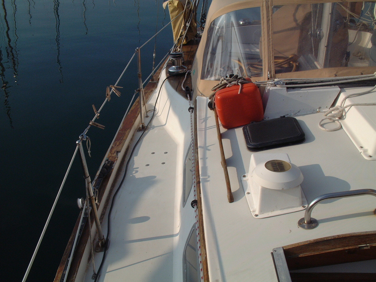
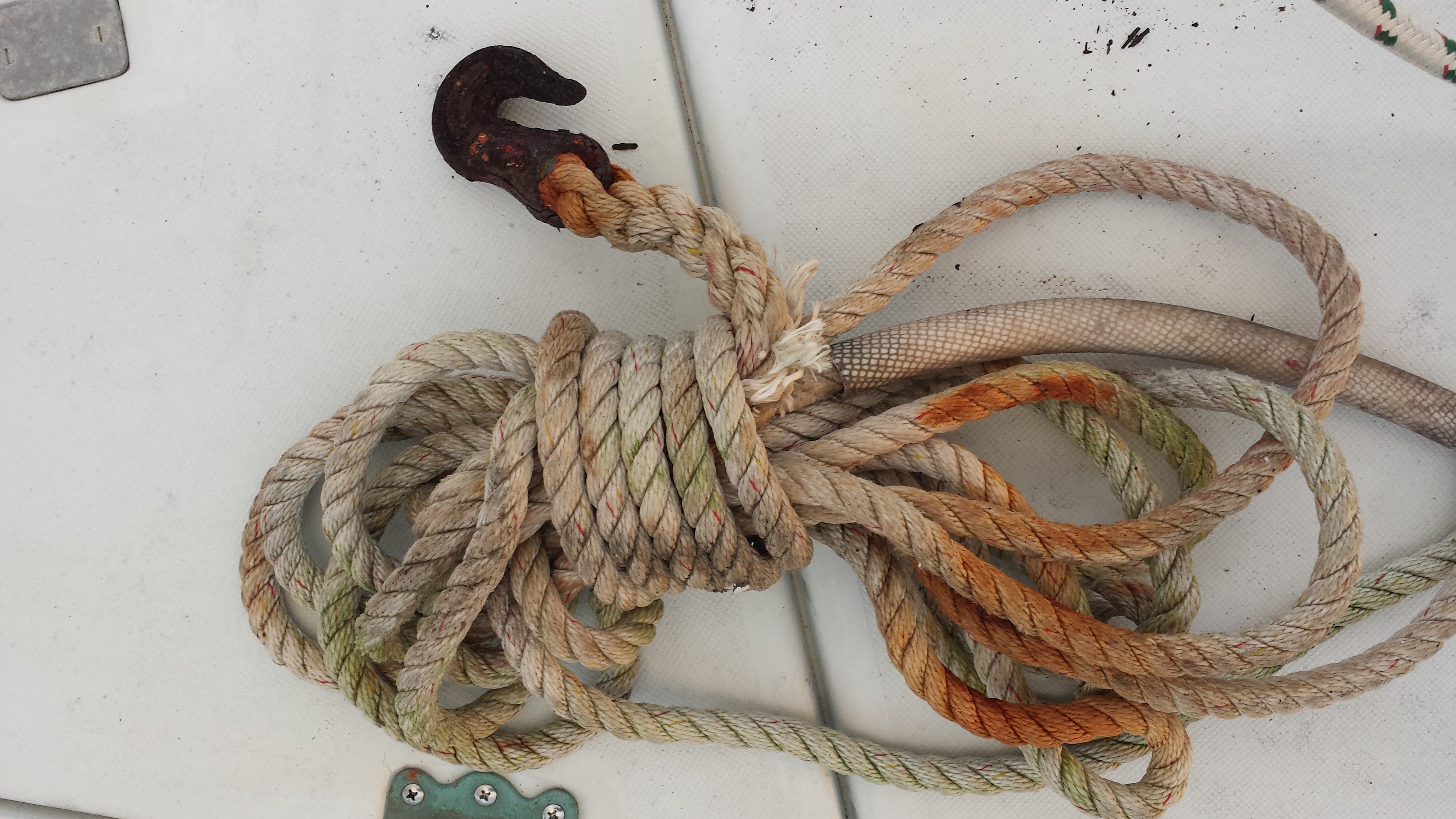 Anchor Snubber Line with Metal Chain Hook |
When I converted my anchor rode to all chain (see above) I needed to add a chain snubber to my anchor equipment. One of the problems with all chain rode is that it is non-elastic (except for the slack in the catenary) and surges and waves transmit the shock load directly to the mooring fitting on deck. The normal solution to that problem is a rope snubber line as shown in the picture on the left. This snubber is made from 1/2" 3-strand nylon, which provides an adequate level of elasticity for the anchor rode. |
|
I've had a lot of problems with the snubber line shown above because of the
chain hook that secures it to the chain link, not just because the rust shown on the
picture above. This type of chain hook tends to fall off the chain when paying out the anchor rode and when the rode goes slack. Many times I been awaken at night with the sound of the chain moving and pulling on the mooring cleat. I then have to get up on deck and resecure the chain hook to the chain. In 2013 I started evaluating a replacement to the metal chain hook with a soft shackle as shown in the pictures on the right and below. |
 Soft Shackle |
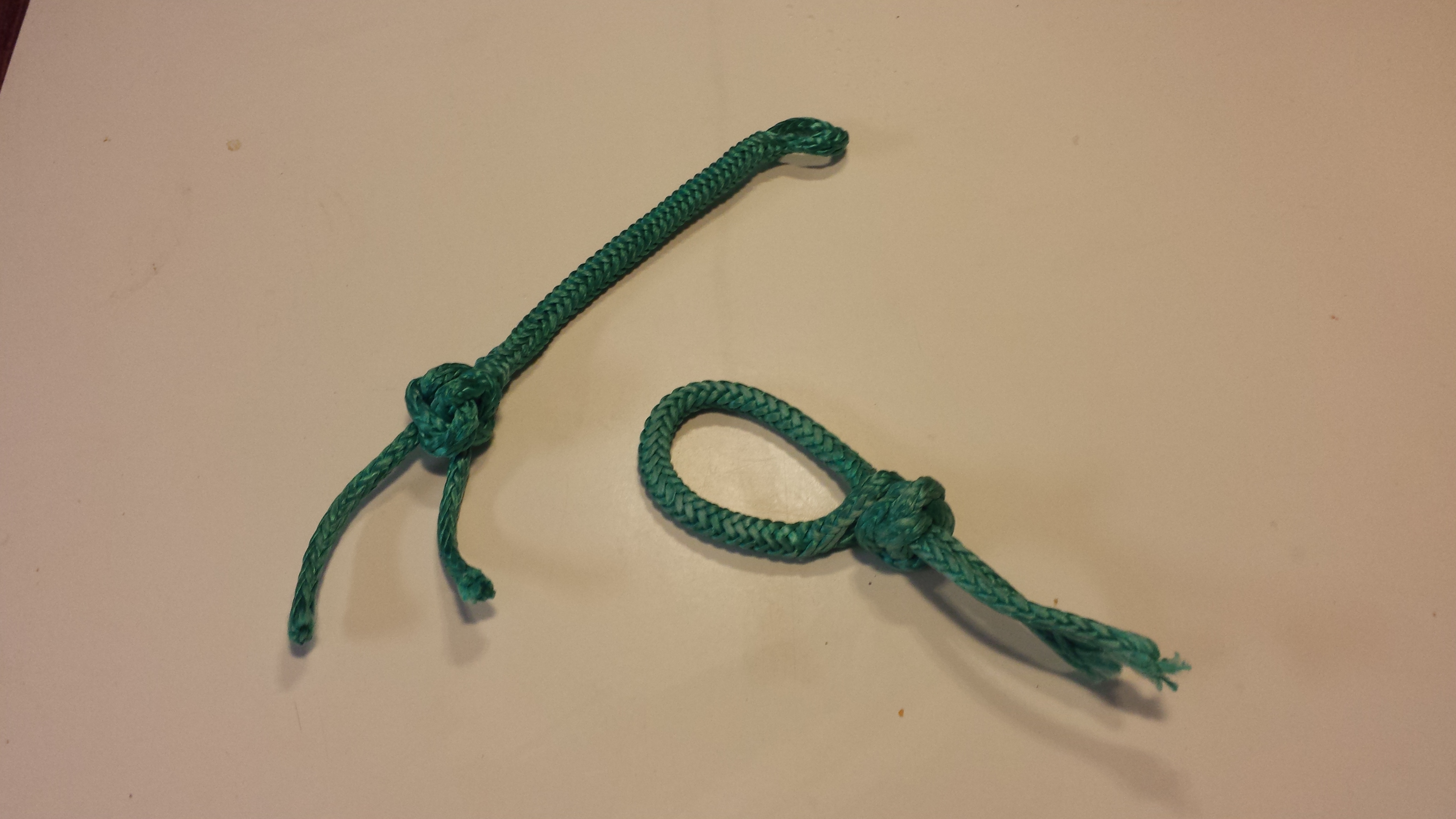 Open Shackle (Left), Closed Shackle (Right) |
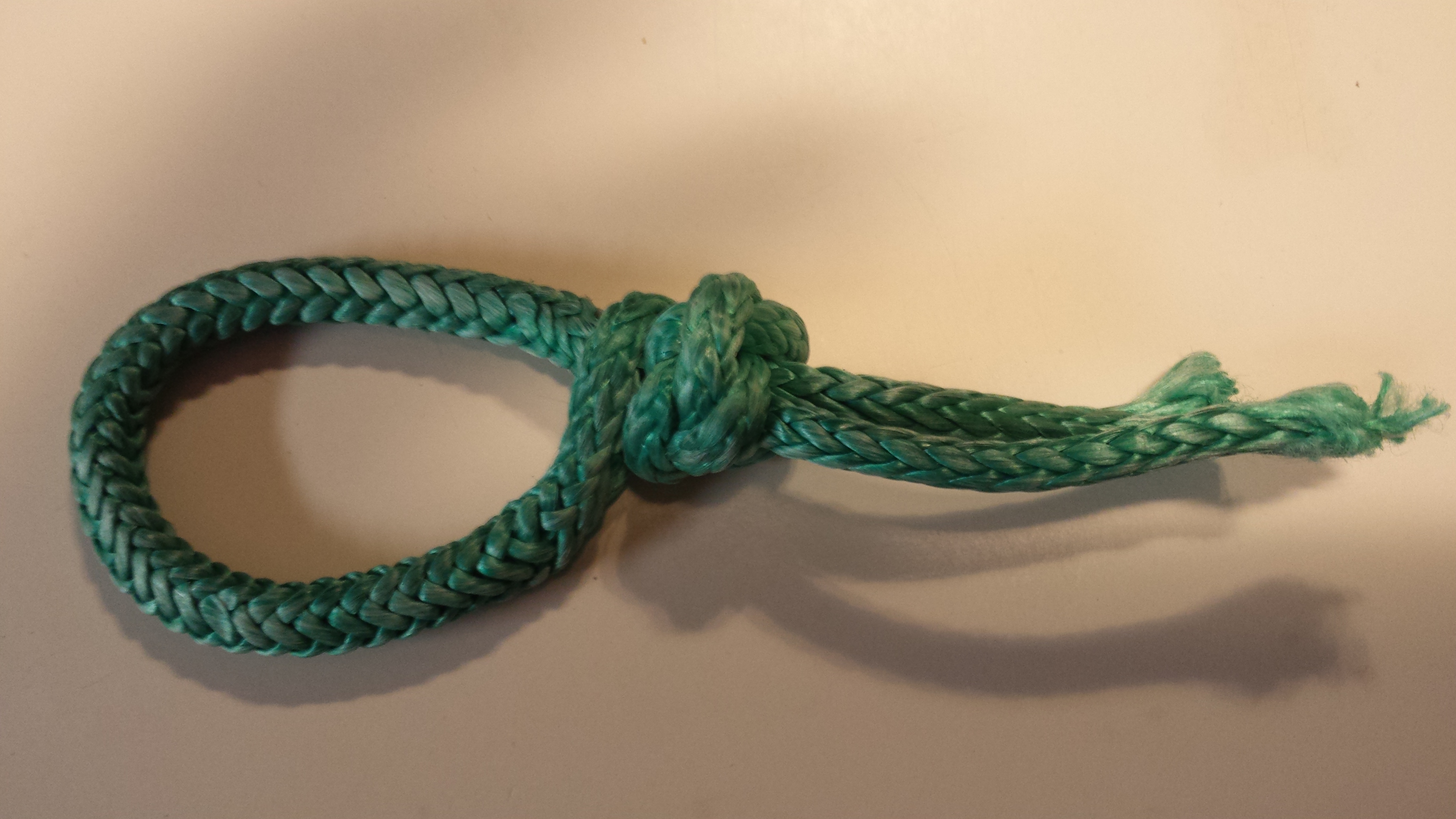
A soft shackle is simply a short section of Dyneema (Amsteel, Spectra, etc.)
line that has been configured as shown in the picture on the left. I learned of this device on the Cruiser's Forum and learned how to make it on the the L-36.com website. To understand how this piece of rope works, is created and used go to the L-36.com website. The soft shackle is made up of an loop spliced at one end and a stop knot (diamond knot) at the other. The loop can be openned by sliding the outer cover down and slipping the loop over the stop knot to create the shackle. The open shackle is shown on the left side of the picture, the closed shackle is shown on the right. When a load is placed on the shackle the loop jams up against the knot. |
|
Based on the recommendation of L-36.com website, I've left the tails of rope
below the diamond knot intact. The expectation is that once the shackle
is put under a heavy load for an extended period of time the knot will
harden and suck in some of the tails. After I've used these shackles
with the snubber line on Sarah's anchor for a week or so, I may cut off the
tails. These shackles were made from Samson 3/16" Amsteel single braid line. I chose 3/16" line because it is easy to pass the shackle through a link of my 5/16" G40 chain. This line has a breaking strenght of 5,400 LBs. The line strength is somewhat deminished by the knot and splice, but the shackle is constructed of a double line to more than compensate for the loss. The eye splice is made up by passing one section of the line inside the other, hence the two tails that exit the diamond knot. The 1/2" snubber line has a breaking strength of 7,500 LBs. The breaking strenght of the chain is more than 20,000 LBs. |
|
|
In order to use the soft shackle with a snubber line I cut off the chain
hook and spliced an eye in the snubber with a stainless steel thimble.
The soft shackle will connect the eye in the snubber to one of the links in
the chain rode. |
 Snubber Line With Eye Splice for Shackle to Chain |
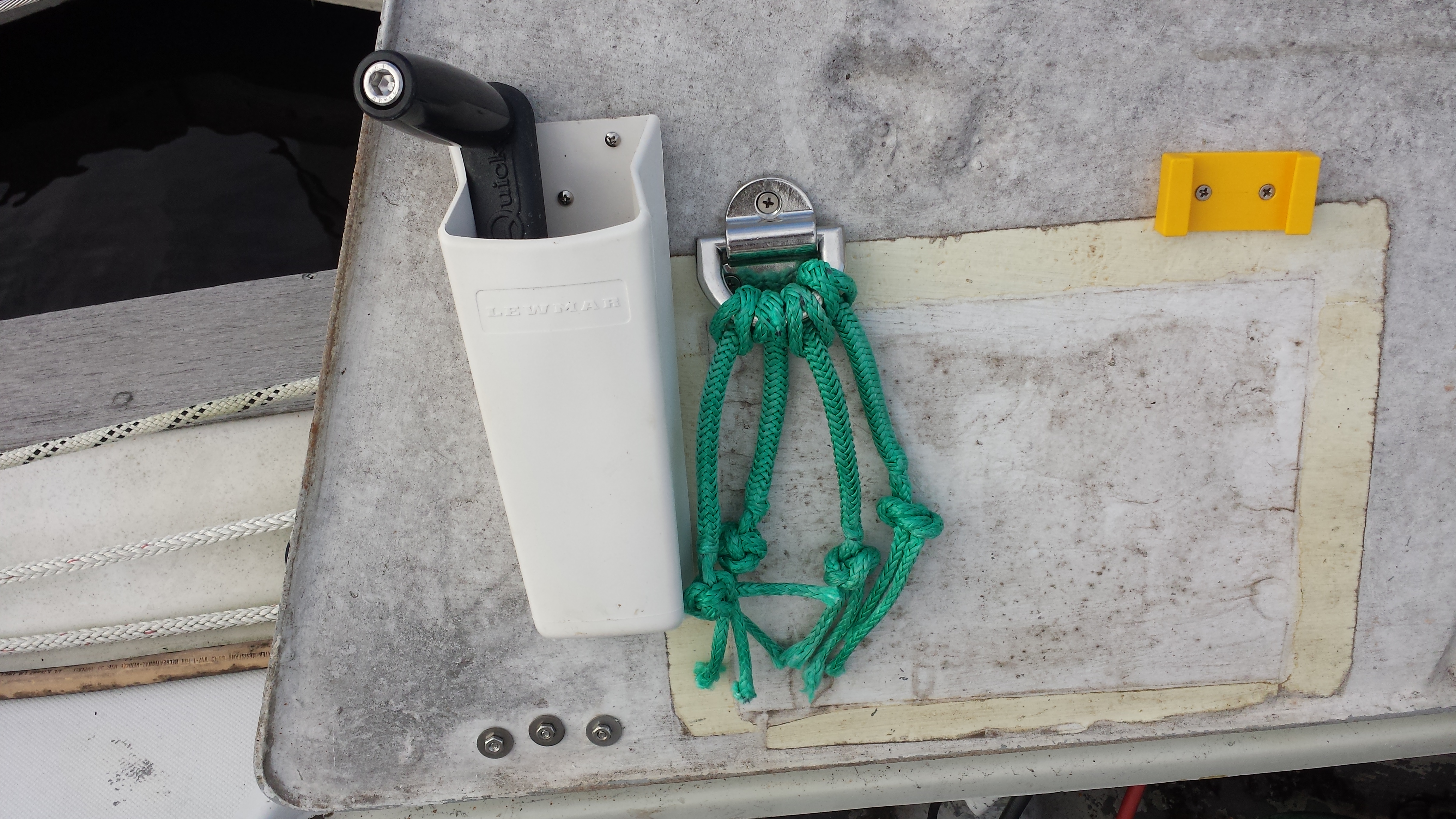 Four Soft Shackles Hung on the Anchor Locker Hatch |
For now I have made up four (4) soft shackles for the chain snubber. I installed a folding padeye on the underside of the anchor locker hatch and hung the shackles on this padeye. The shackles will be immediately available when I am in the process of anchoring Sarah. |
| I used these shackles over the winter of 2014 in the Bahamas, and they were a great improvement over the metal chain hooks. After several months, and more than a few winter storms at anchor there was no sign of chafe on the soft shackle. | |
| Anchor Windlass | |
|
When I purchased Sarah in 2000 she was equiped with a Lofrans Royal manual
windlass (shown on the right). This was adequate, but not ideal for
the initial ground tackle that I added to Sarah - 44 Lbs Bruce anchor and
50' of 3/8" chain. When I converted to all chain rode in 2008 it was
less than adequate, but still workable. In 2009 I replaced the Bruce
anchor with a 60 Lbs Manson Supreme anchor and the windlass was a problem. |
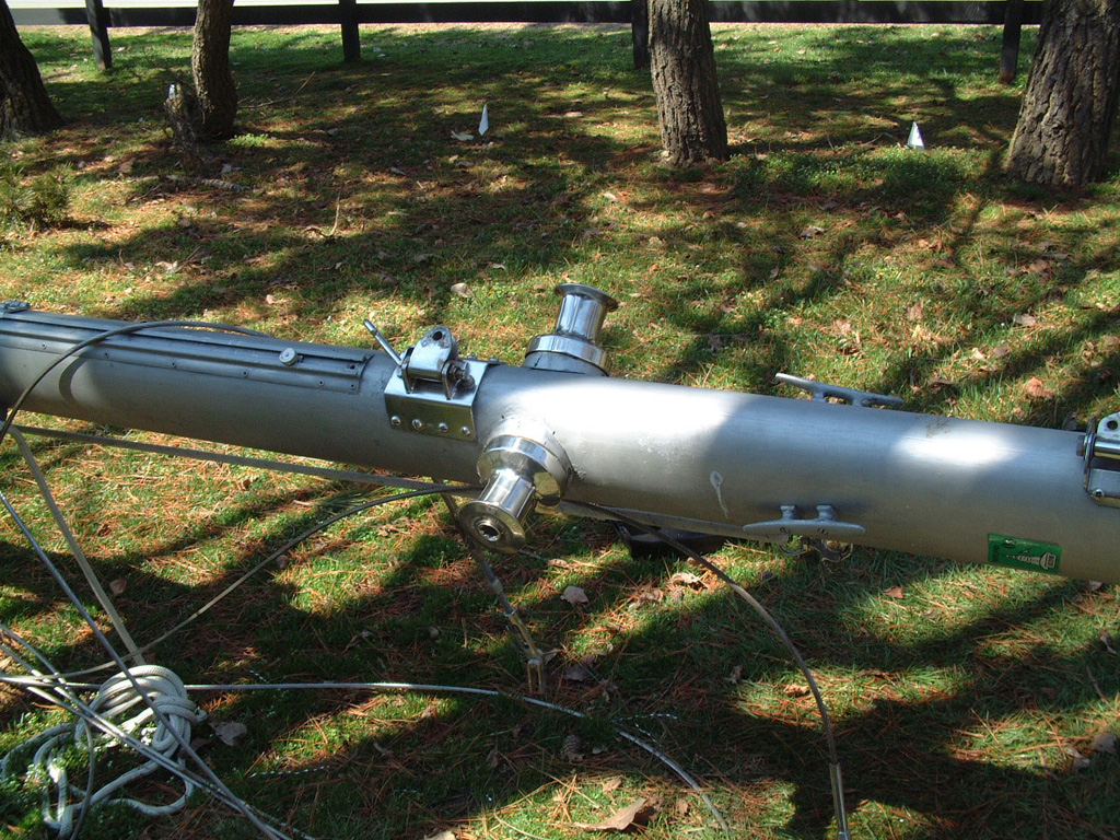
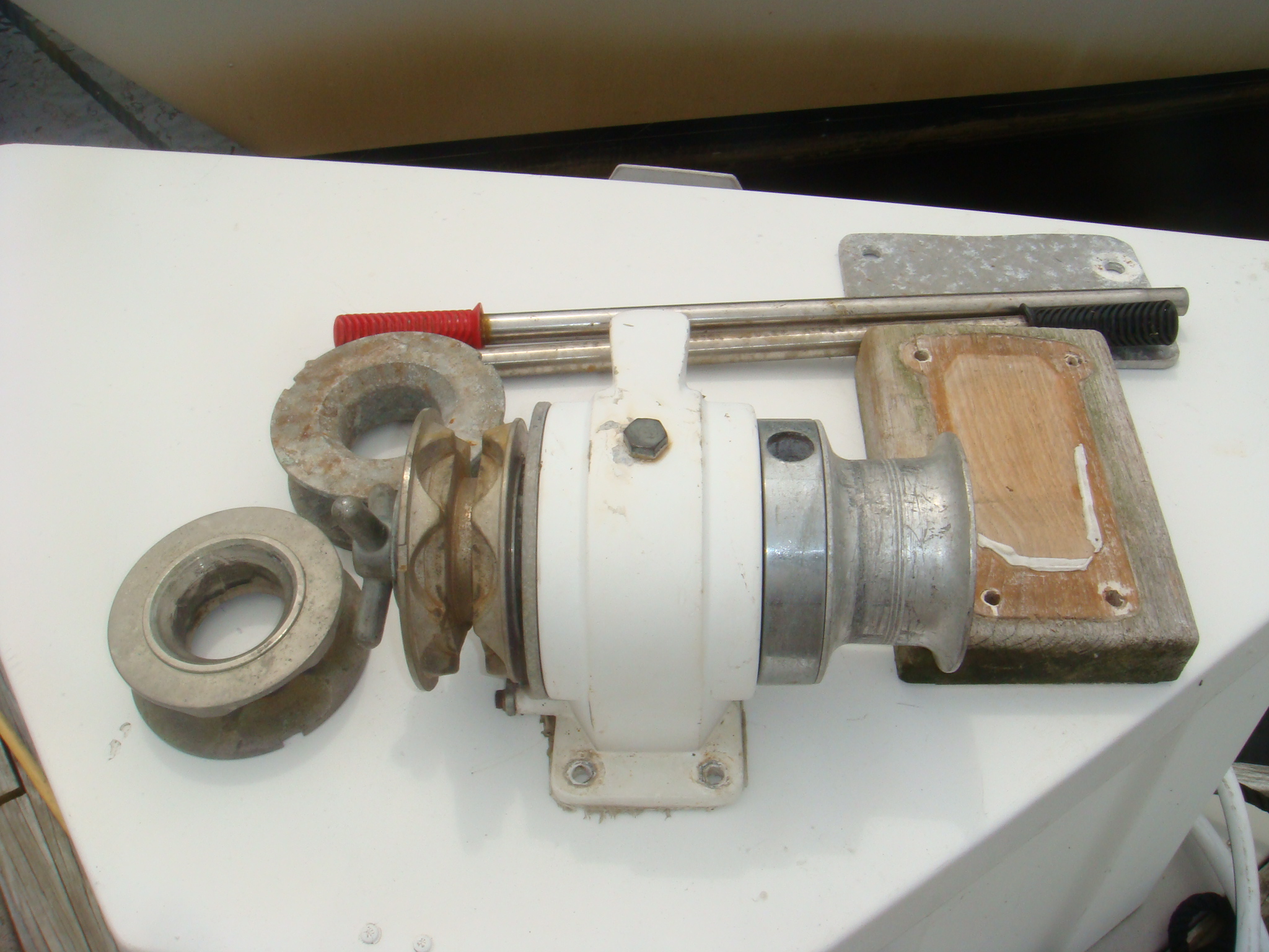 Lofrans Royal Windlass After De-Installation |
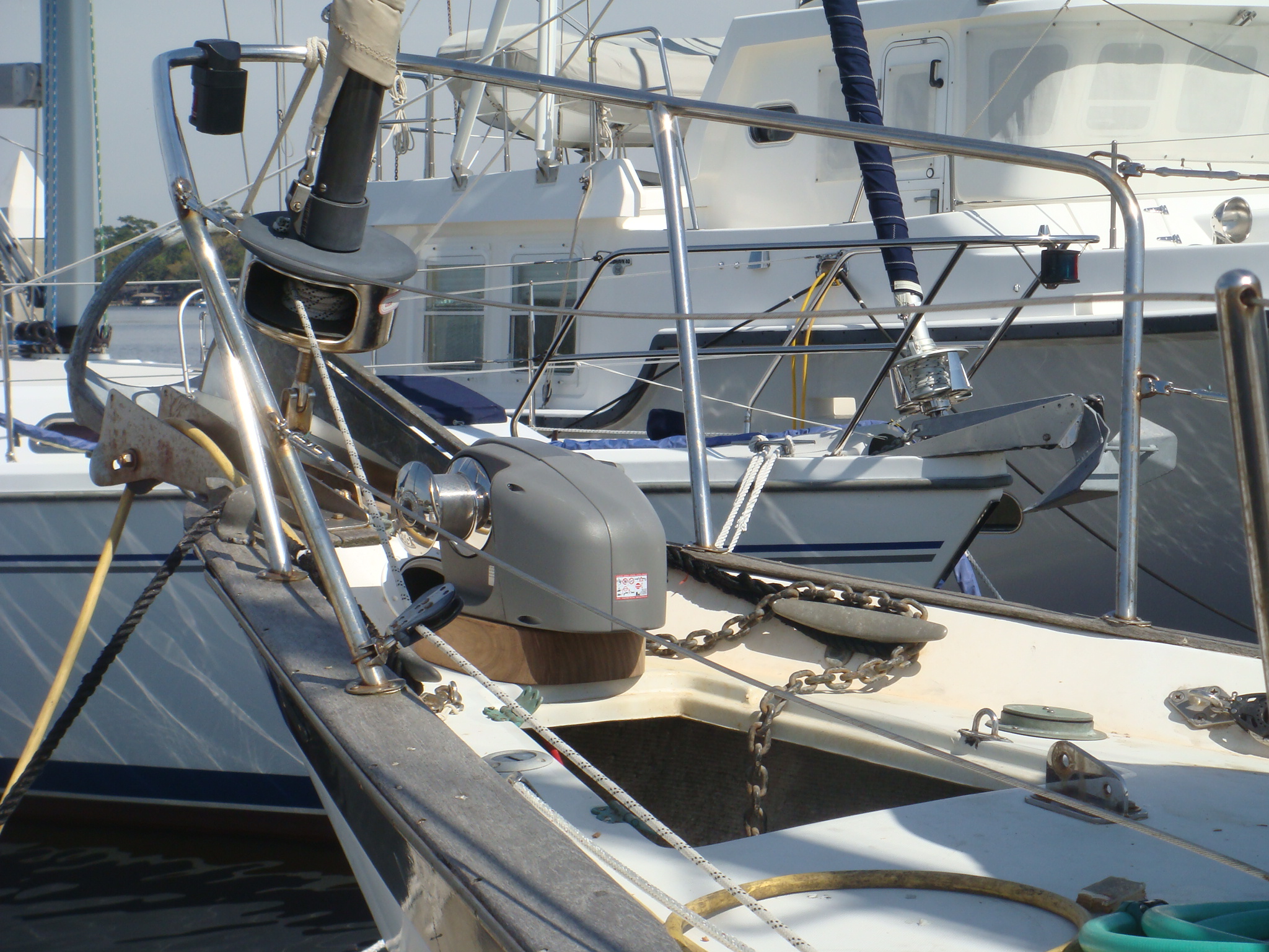 Quick Hector Windlass During Installation |
I lived with the Lofrans for several more years, but then in 2012 I
purchased a Quick Hector electric windlass and replaced the Lofrans. I have published a separate page on the installation and operation of this windlass. |
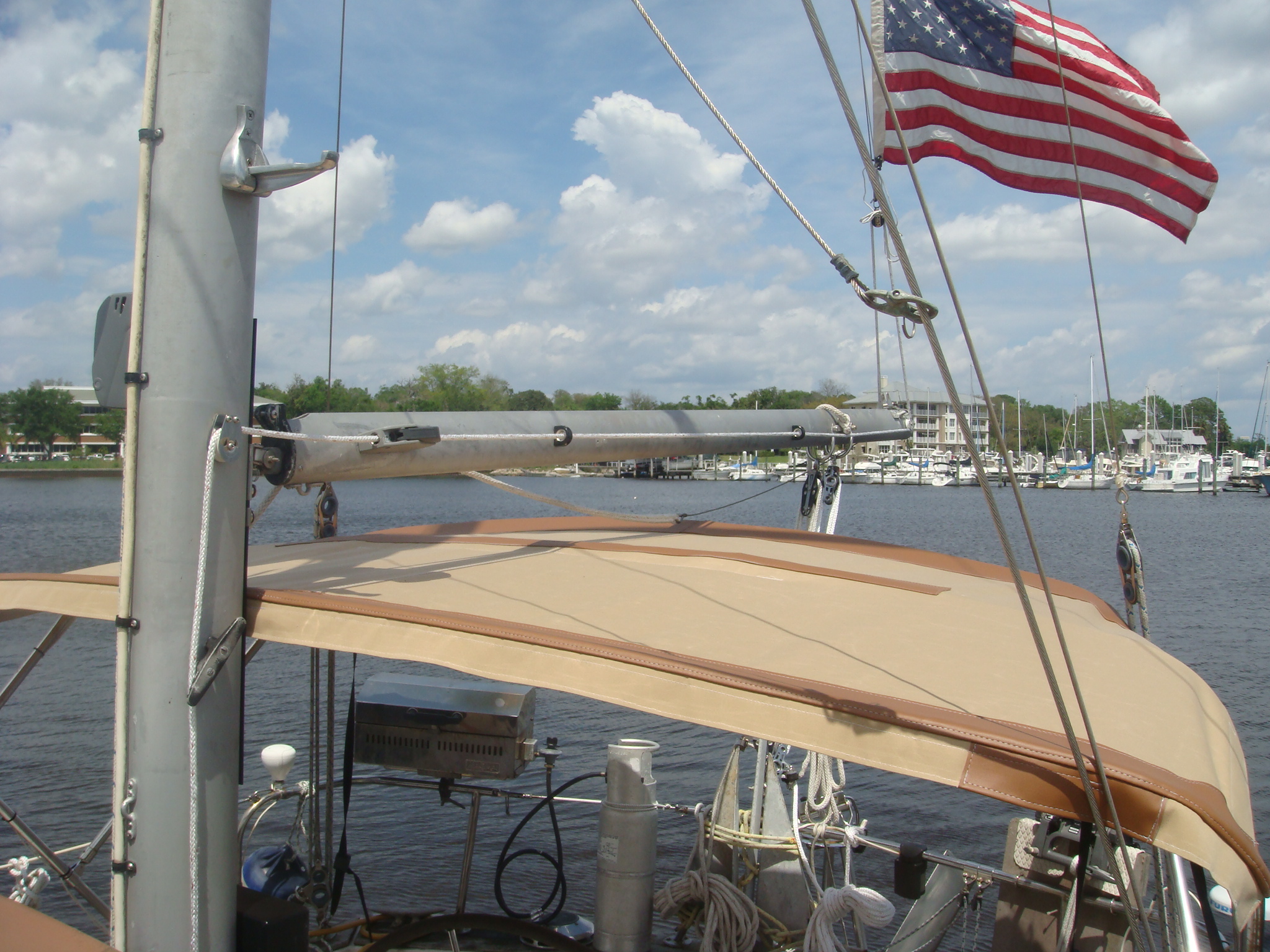
| Running Rigging - Mizzen Mast, 2001-2012 | |
| With encouragement from Jack Tyler I replaced the mizzen sheet arrangement from a lead to a winch on the mast with a 4:1 set of blocks and a cam cleat. The mizzen certainly doesn't need a winch to trim (unless I get really feeble in old age). Even this new arrangement is overkill, but it was the cheapest tackle available in West Marine at the time I went into the store. The primary reason for this change is to allow Leonard Canvas to maximize the height and forward reach of the bimini I have ordered. It will have the additional advantage of freeing the mizzen mast winch for a mizzen staysail halyard. |
 New Mizzen Sheet Mounted on the Stern Rail |
 Dual Tackles on the MIzzen Boom |
One of the adavantages of this sheeting arrangement is that, when sailing
off the wind, I could move the lower block to the deck padeye for the lazy
backstay. This allowed the sheet to act as a vang and maintain good
control of the sail, especially in strong winds. Those strong winds, however; also demonstrated the weakness of this rig. In order to move the sheet block from the rail to the padey;e I had to hold the sail by hand until the snap shackle was secured to the padeye. On the way from Madeira to Bermuda with over 35 kts of wind on the quarter this was a real challenge. I stayed with the mizzen sheeting arrangement, and its weakness, for over 8 years. Then in 2012 I added a second tackle as shown in the picture on the left. |
|
The second tackle, made up of Garhauer blocks, is attached to the
second bale on the boom. Now when I need to sheet the mizzen to the
deck padeye, I let out one sheet and release the other, which is moved to
the padeye. This gives me a separate sheet and vang. With the dual tackles I always have the boom secured when moving the vang tackle. Also, having two sets of tackle on the mizzen made it easier to use one of the tackles as a crane to lower the outboard motor from the stern reail mount to the dinghy and bring it back on board. The other tackle is used to hold the mizzen boom in place during this operation. |
 Tackles on Separate Boom Bales |
 Running Backstay with Garhauer Blocks and StaSet-X Line |
Replaced old Schaeffer blocks on the running backstays with Garhauer blocks. 25 years of sun had killed the plastic sheaves in the old blocks. |
| When I added the Bimini cover over the cockpit the control lines on the mizzen boom suddenly became difficult to reach. The outhaul, topping lift and reef line were all cleated mid-boom, which made them convenient to the helm before the cockpit was covered. With the Bimini in place I had to stand on the stern coaming or the bridge deck and reach over the Bimini to adjust one of the lines. This arrangement didn't exactly provide for a lot of leverage on those lines as well. | |
|
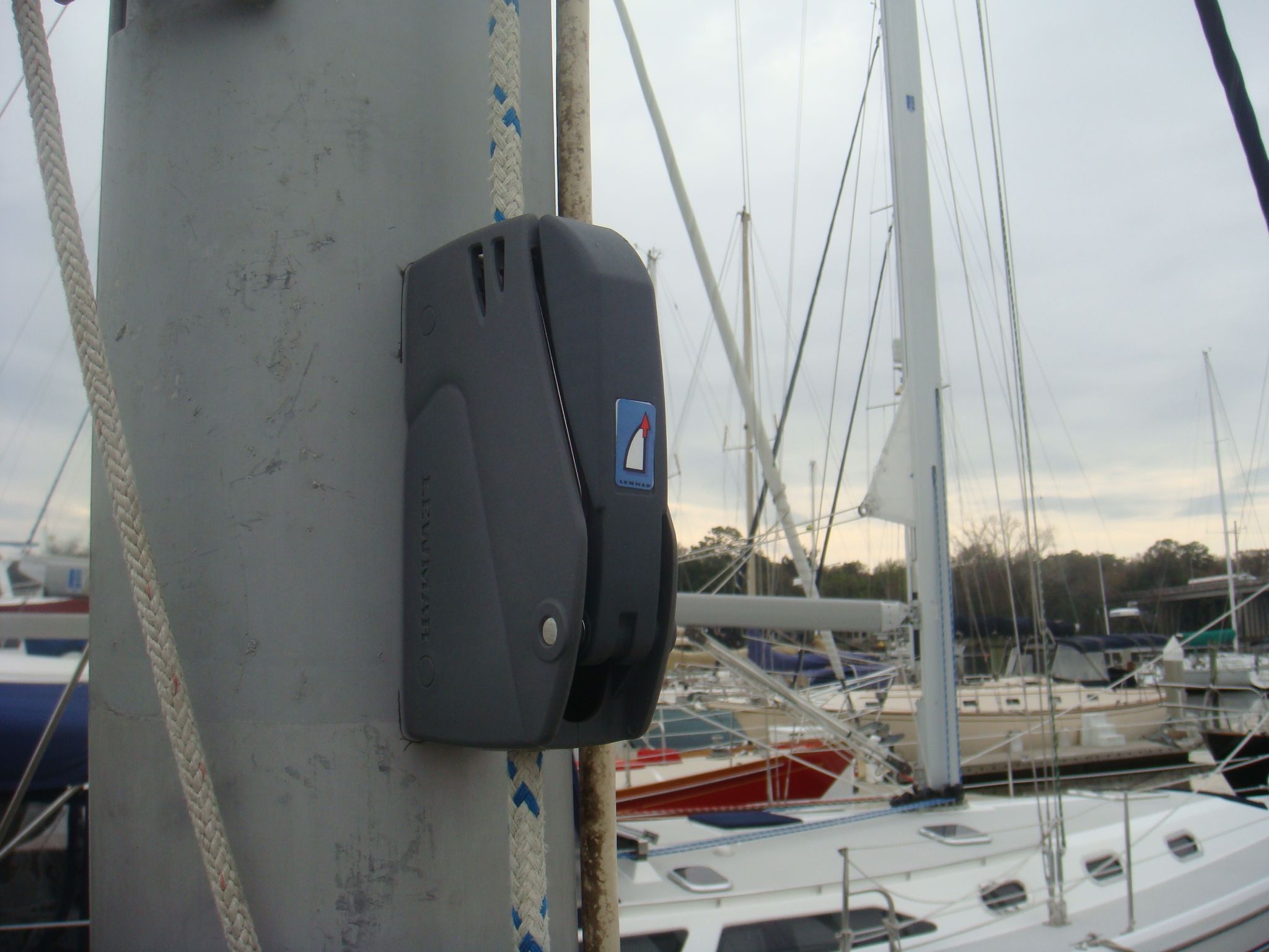
To correct the problem I replaced the cleats on the starboard side of the boom with a double Lewmar D1 clutch. This is the same clutch I use on the main sail boom for the reefing lines. The mizzen clutch is close to the goose neck, over the forward edge of the Bimini so it is easily reached. This clutch takes care of the outhaul and the reef line, the two lines that need a little leverage.
|
 Rope Clutches for the Mizzen Outhaul and Reef Clew |
 Original Rig for the Mizzen Topping Lift |
On the port side of the boom I left the topping lift on a cleat. This cleat is on the aft portion of the boom and can be reached by someone as tall as I (>6'), but only by standing on the stern coaming and reaching back over the top of the Bimini. I could not get my hands on a single D1 clutch at the time I was making these modifications so I left it alone. I planned to replace that cleat over the winter (2004). |
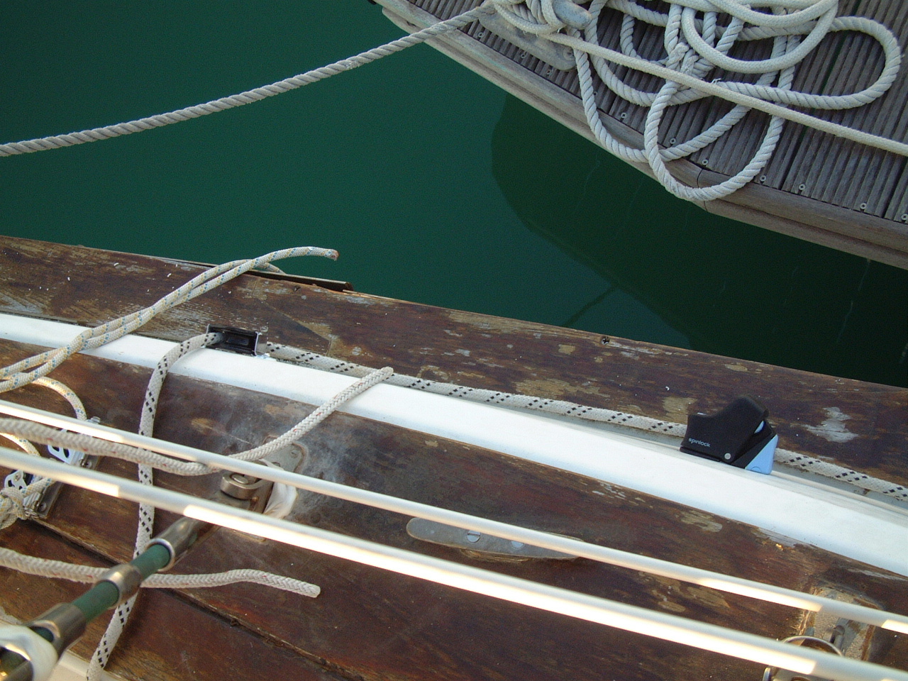
| Well that rope clutch was finally installed on the mizzen boom in 2012, as shown on the right. Now I can easily reach the clutch to secure or release the topping lift from within the security of the cockpit. |
 Topping Lift Rigged to Rope Clutch |
 Topping Lift Rope Clutch |
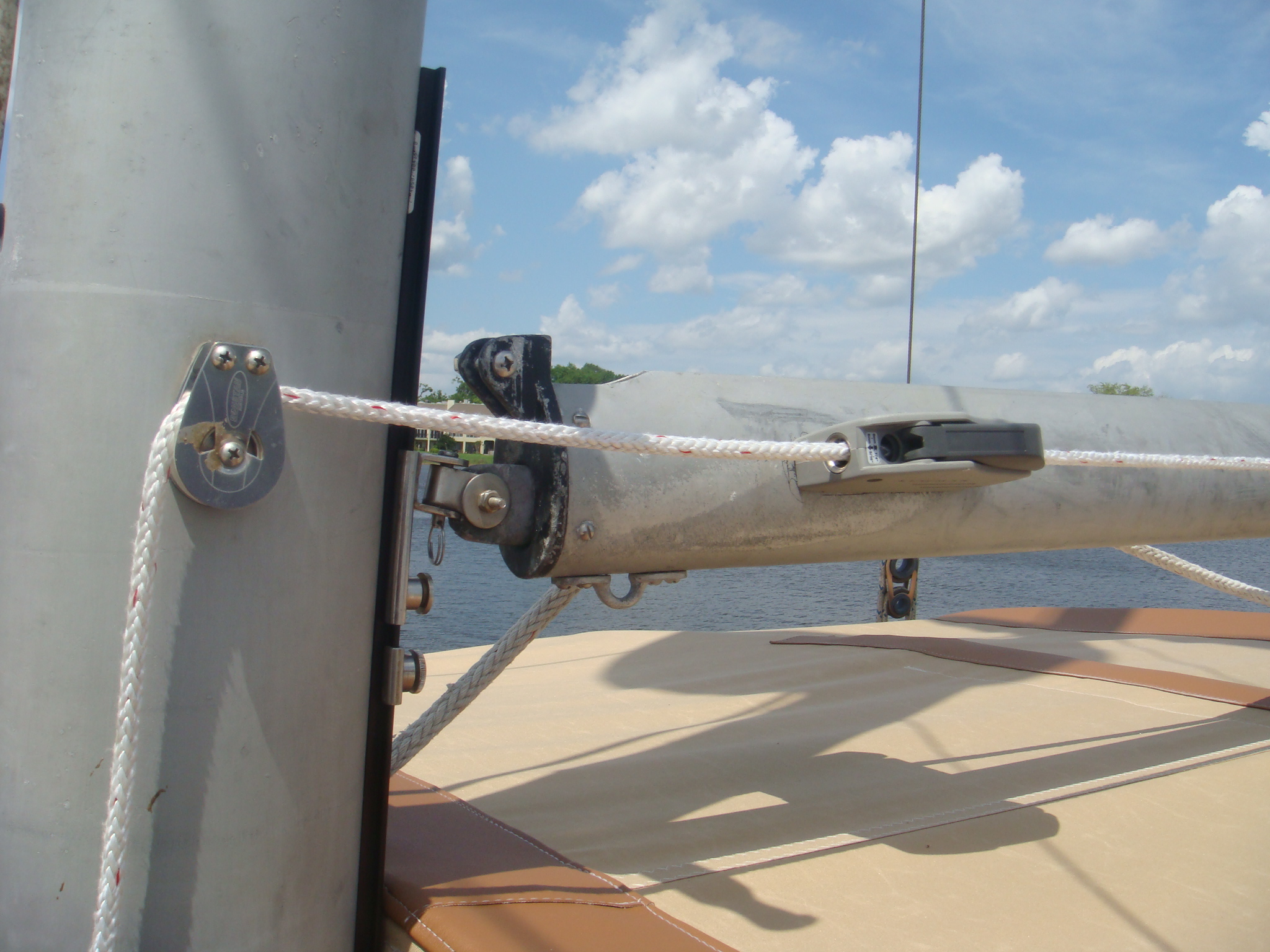
The rope clutch is at the forward end of the mizzen boom. I led the topping lift through a cheek block on the mizzen mast. To raise the topping lift I just pull down on the line and the clutch holds the line in place when I release. |
|
The mizzen halyard really didn't have significant short comings, but I just
decided to add a rope clutch on the mast to secure the halyard. I have
rope clutches on all of the other halyards on Sarah and didn't see any
reason to leave the mizzen out. The real reason is I had a clutch in my parts bin and had no other planned use for it. |
 Rope Clutch for the Mizzen Halyard |
 Folding Step on the Port Side of the Mizzen Mast |
If I ever mount a wind charger on the mizzen I will need mast steps to
service it. I also need steps to secure and release the top of the
mizzen sail cover. I put a folding step on starboard side, above the
halyard winch. In Feb, 2012 I mounted another folding step on the port
side of the mast. This will allow me to stand on the mast with my feet
above the Bimini. I have three more folding steps in my parts bin, enough to allow me to climb to the radar array and service it when necessary. I won't install those until I have a reason to unstep the mast (wind charger install, perhaps?). |
|
Pearson didn't exactly over-engineer the mizzen
boom gooseneck attachment. They just inserted a 3/16" bar of aluminum
into the mast track and bolted a piece of 1" T-Track through the aluminum
into the mast wall. Then they put a car on the track and called it a
gooseneck. The original T-Track is shown on the right. There was nothing wrong with this approach. It had the advantage that the mizzen boom could be raised without having to drill any more holes in the mast. This is something I did to allow more head room for the Bimini. |
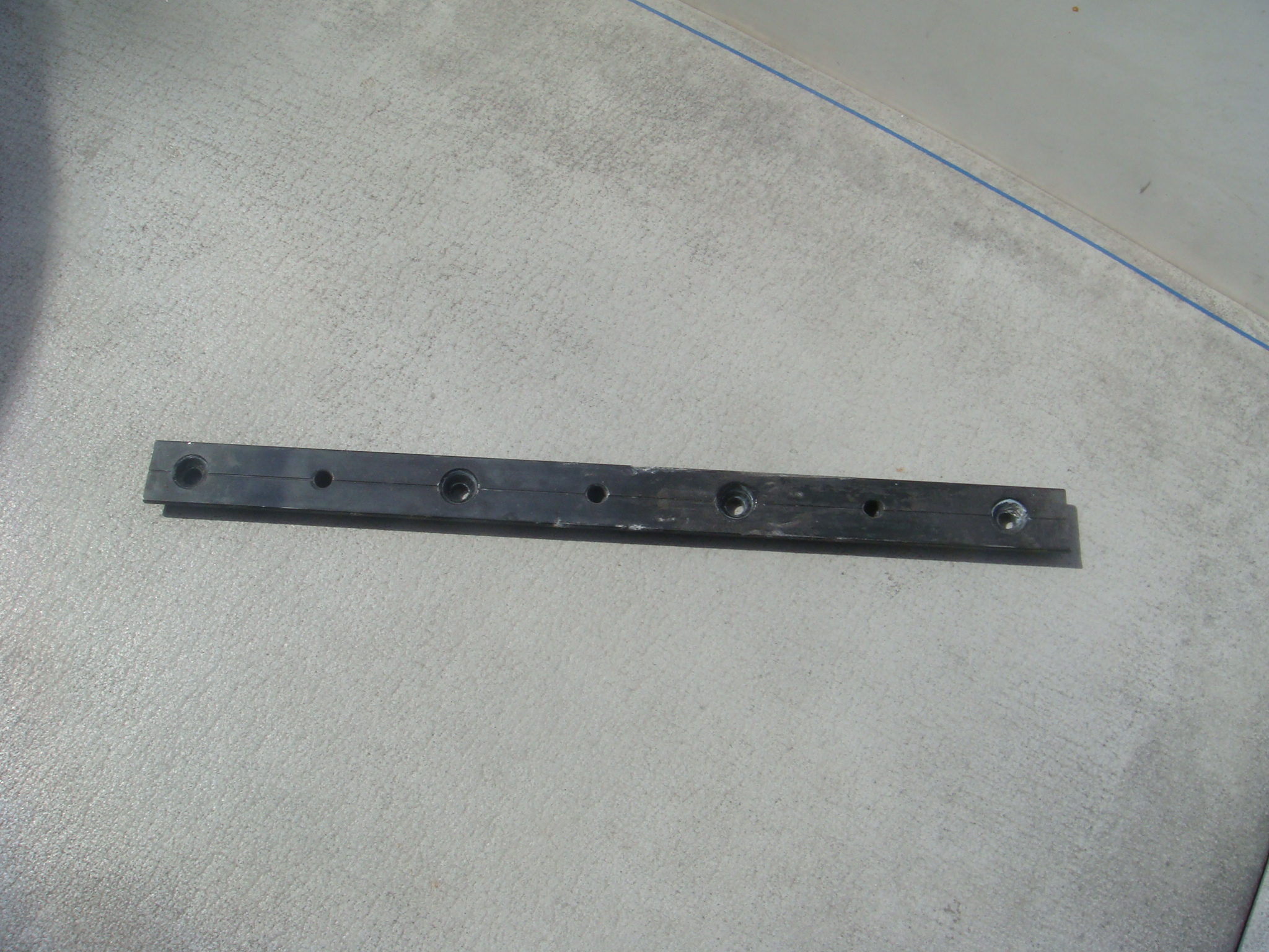 Original T-Track From Mizzen Mast |
 Longer T-Track on Mizzen Mast |
However, the track length and position did not allow the boom to be raised
enough to allow the Bimini to be dropped and secured. My only choice
is to remove the Bimini if severe weather (e.g., a Hurricane) is
threatening. While I had the boom off the boat for the topping lift
rope clutch installation I decided to lengthen the T-Track to allow the boom
to be raised sufficient to lower the Bimini. The new track is shown on the left and below. |
| In order to install the longer track I needed a longer piece of aluminum, which a local rigger provided. On the right is picture of the track and the car that functions as a gooseneck. The car is held in place by a spring tensioned stop on the track. That is not the most secure way to hold the car in place and it would often slide down such that the boom was resting on top of the Bmini. To prevent this I added a screw down track stop below the car. That will hold the boom in place should the spring stop slip. |
 Side View of T-Track and Mizzen Gooseneck |
| Running Rigging - Main Mast, 2003 | |
 Internal Halyards on the Main Mast |
In 2003 I converted the halyards from external to internal. This provided one
additional jib halyard and added an adjustable topping lift to replace the
harbor lift for the boom that is attached to the mizzen mast. This topping
lift could also be used as an emergency replacement for the main halyard.
The internal halyards also eliminated a lot of halyard chafe at the
spreaders, reduce halyard noise at the dock and at anchor, and generally
cleaned up the mast area. For details on this conversion see the 2003 Rigging Overhaul page. |
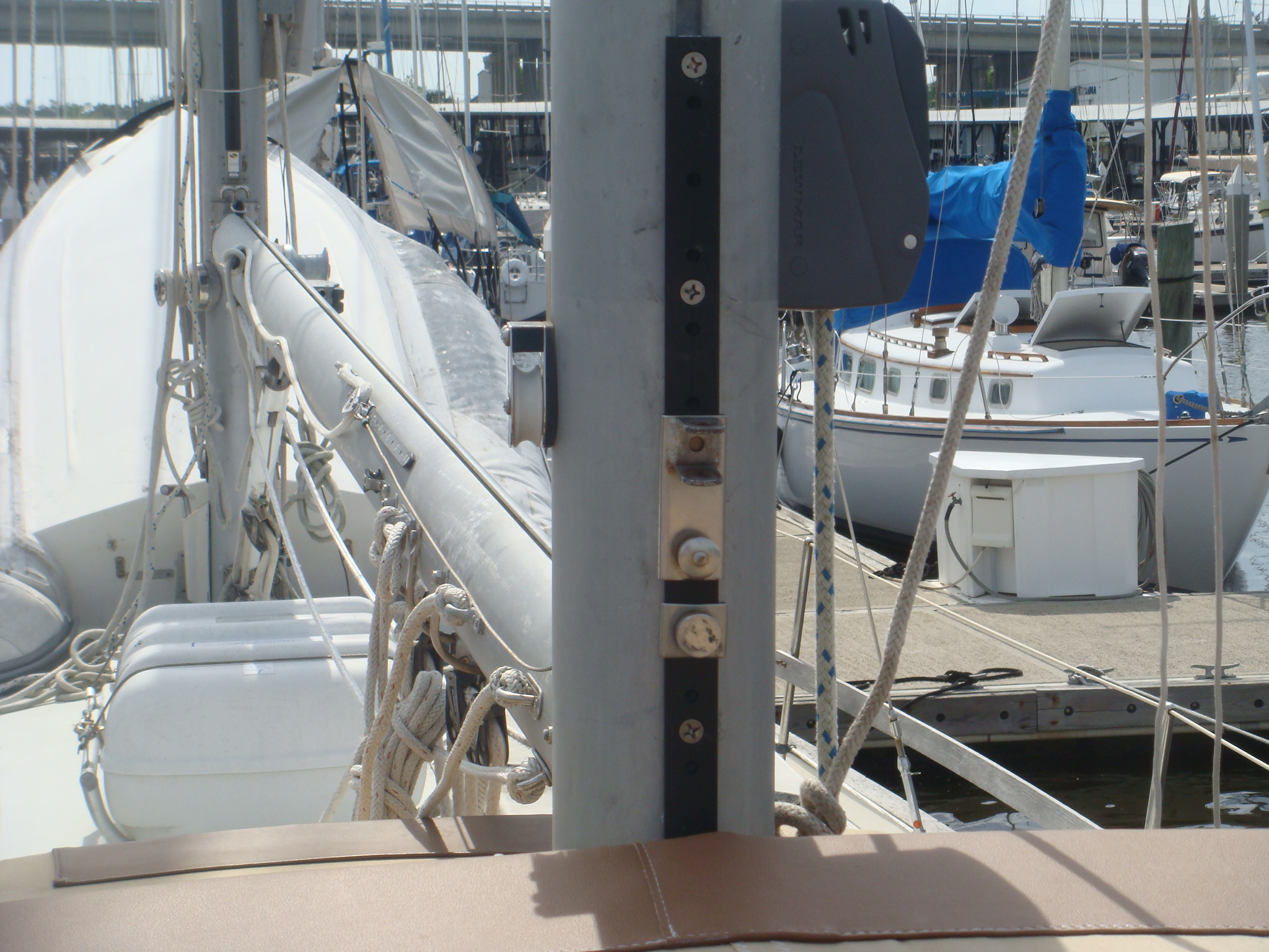
| In 2000 I
added Lewmar Rope Clutches to secure Genoa and Spinnaker halyards, and
replaced all halyards, including the main and mizzen. With the conversion to internal halyards in 2003 I had two Genoa halyards, but only a single rope clutch (picture on left). |
 Spinnaker and Genoa Rope Clutches Before Conversion to Internal Halyards. |
 Double Rope Clutch for Two Genoa Halyards |
Subsequently I replaced the single Genoa halyard clutch with a double clutch to accommodate both halyards (picture on left). |
| I used the freed up single clutch to put a rope clutch on the mainsail halyard as well (picture on right). Now all halyards, including the topping lift, are secured with rope clutches. |
 Rope Clutch for Mainsail Halyard |
 Rope Clutches on the Mizzen Boom |
I also added double rope clutch on the main boom for the reef lines. |
| The line for the first reef is on the bottom clutch. |
 Closeup of Main Boom Rope Clutches |
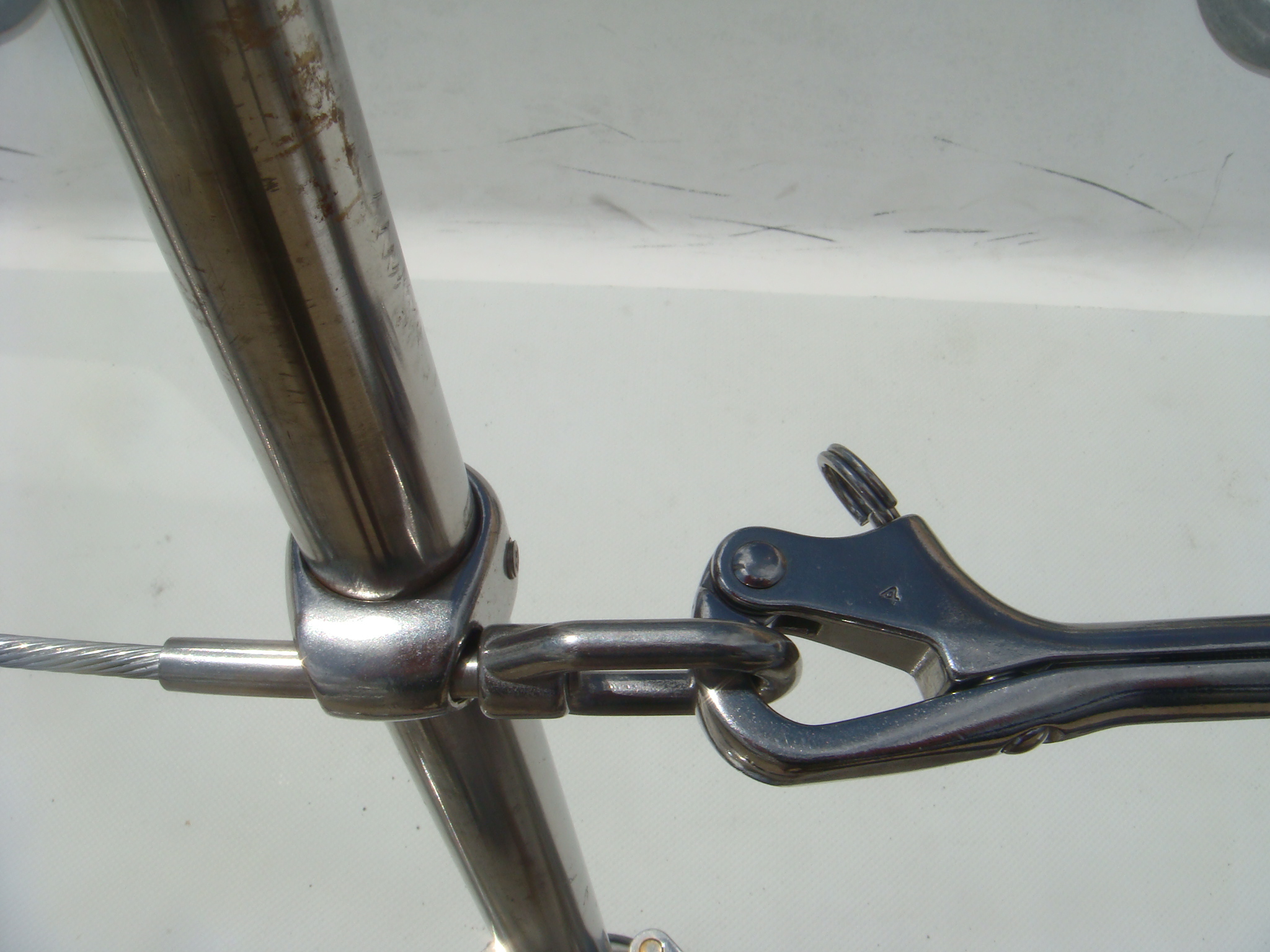
| Standing Rigging, 2007-2013 | |
 Broken Wire Strands on the Port Forward Lower Shroud |
It is difficult to see in the picture on the left, but shortly after I sailed Sarah back from Europe to the Chesapeake Bay I discovered that the port forward lower shroud had started to break at the turnbuckle fitting. If you click on this picture to download the full resolution image you can see that several of the wire strands have separated at the top of the turnbuckle. This was the original 30 year-old rigging installed by Pearson or the dealer when the boat was first commissioned. |
I had the rig surveyed before we left Florida on the Atlantic Circle, and I also went over the rigging myself before we left Portugal on the return passage. The surveyor recommended I replace the rigging based on the age, but found nothing the required immediate attention. So I departed and made two trans-Atlantic passages on this rigging. I assume this break started while we were sailing back from Portugal. I'm actually glad I didn't notice this until Sarah was safely back in the Chesapeake Bay. If I had discovered it while at sea there wasn't much I could have done about it, but I sure would have worried about it. |
|
| After discovering the break I had all of the main mast standing rigging replaced, wire, turnbuckles, terminals and toggles. All of this stuff was nearly 30 years old, so I think I got good service from it. For the replacement rigging I had Sta-Lok turnbuckles installed on all of the shrouds and stays. For the terminals on the mast I had swaged terminals installed. | 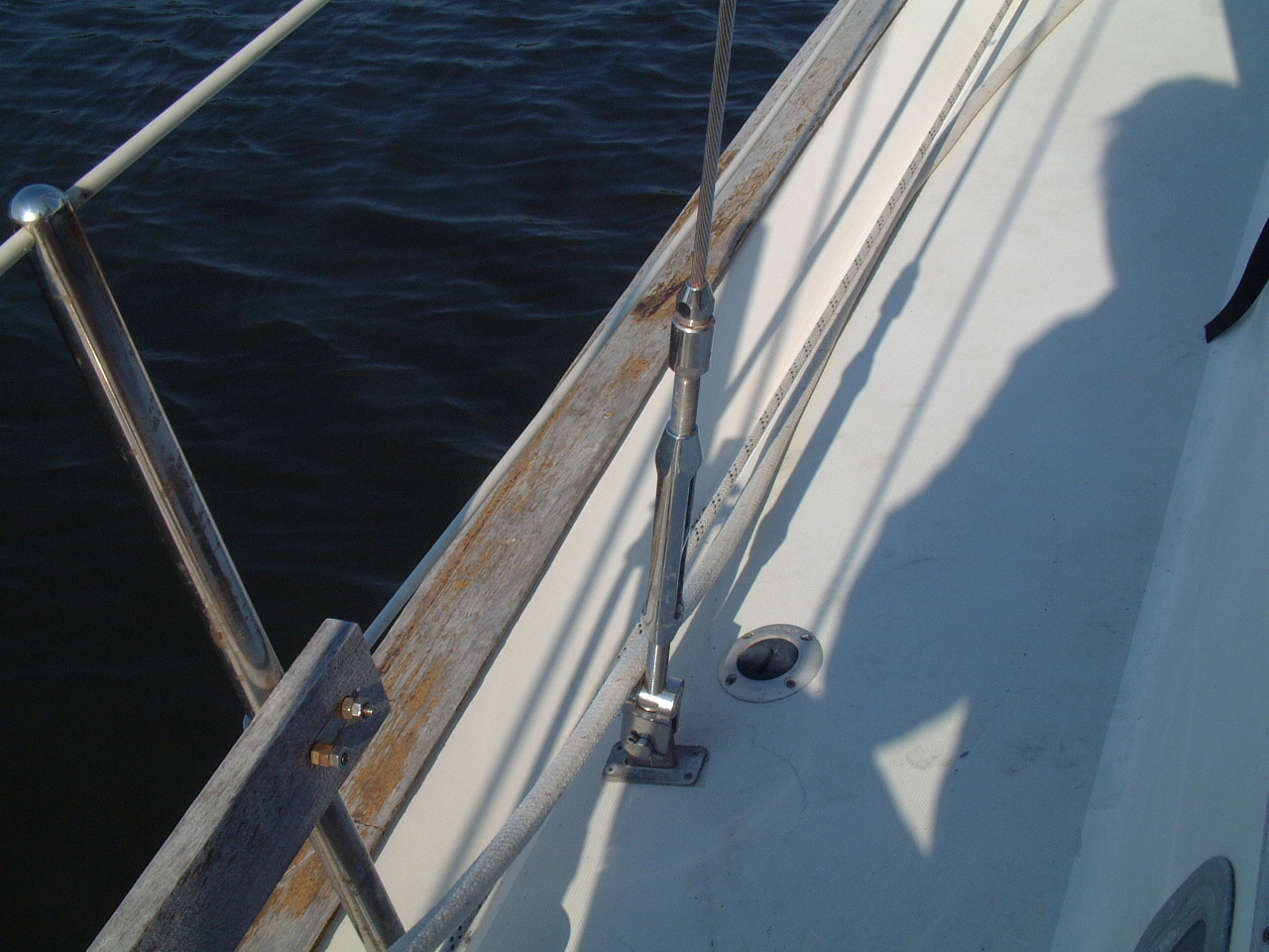 Replaced Shroud and Turnbuckle |
 Sparman, AKA Julian Crisp |
In 2013 I finally replaced the mizzen standing rigging. There
was no apparent problem with the rigging, but it was the original 1979
equipment. For this work I used a local (JAX) rigger, Sparman, who was able to replace the rigging with the mast up and the boat in the water. |
| All of the new turnbuckles are Sta-Loks rather than swaged fittings. |
 Port Upper and Lower Shroud Turnbuckles |
 The Triatic Stay Between the Manin and Mizzen Masts |
In addition to the shrouds, the triatic (AKA freshwater) stay between the main and mizzen masts was also replaced. |
| Winches, 2003 | |
 Andersen Winches on the Main Mast |
Sarah came with a full set of working, but aged Lewmar winches. I replaced the Lewmar 16 & 25 2-speed winches on the main mast with Andersen 16 2-speed winches. The bearing assembly on both of those Lewmar winches were broken. |
| The Lewmar 48 3-speed cockpit winches were still in good working condition, but I really wanted to replace them with self-tailing winches. Also 3-speed winches are pretty much an overkill on a cruising boat like Sarah. In the first three years of sailing Sarah the only time I ever operated the winches in the first gear was right after the annual maintenance just to insure the gear was still working. I replaced the Lewmar 48s with a pair of Andersen 45ST 2-speed winches. |
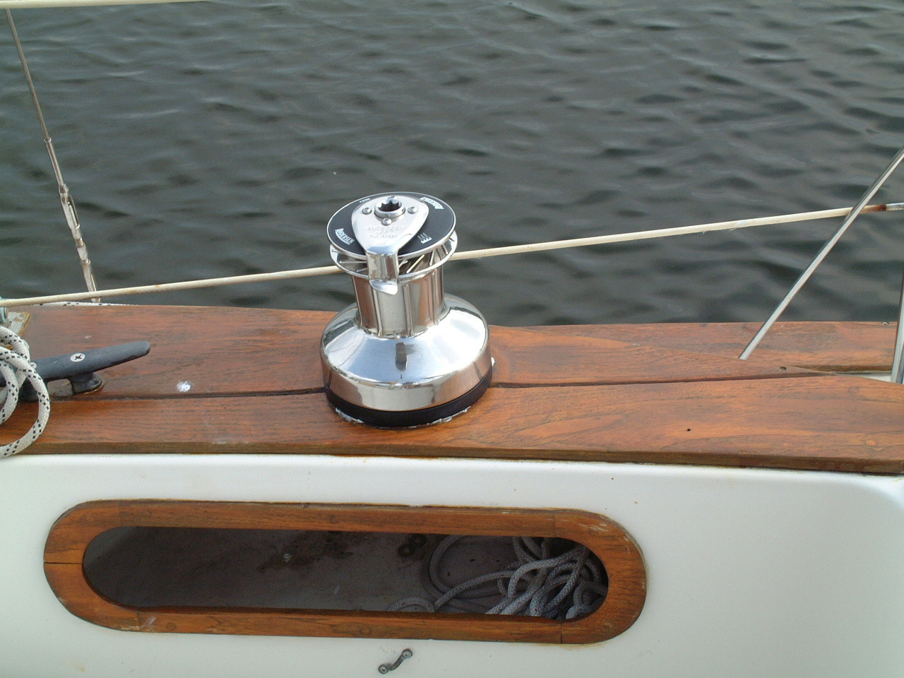 Andersen Self-Tailing Winch for Genoa Sheet |
| Lifelines,2005-2012 | |
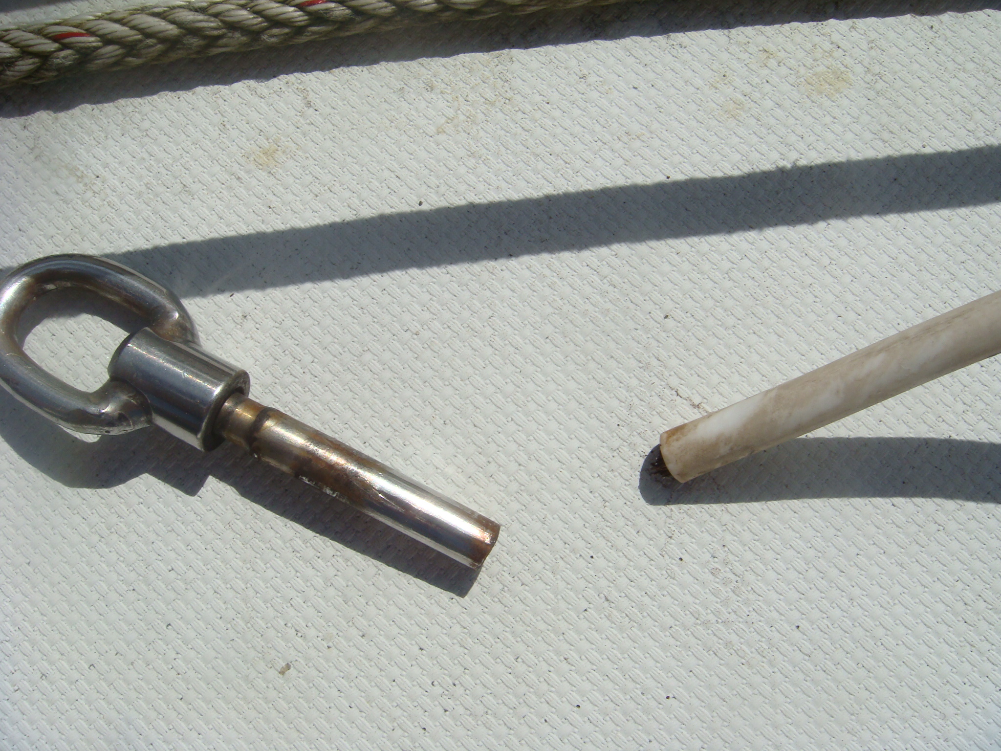 Broken Lifeline, Exposing the Galvanized Wire Core |
The lifelines that were on Sarah when I bought her were
original equipment from 1978. Before departing for Europe
in 2005 I replaced those lifelines and all of the fittings.
I intended to go with bare stainless steel wire, but was talked
into the standard vinyl-coated wire by the rigger I hired to do
the job. The rigger apparently used vinyl-coated
galvanized wire rather than stainless. In February, 2012 one of the lifelines broke under the strain of a couple of fenders, as shown on the left. That is when I discovered the wire was galvanized, not stainless. |
| I briefly considered replacing the lifelines with
dyneema cordage, but finally ordered stainless steel lifelines
from a local rigger in Jacksonville, FL. This time I was
assured that the lifelines would be stainless and would not be
coated with vinyl. The port lifelines are shown in the picture on the right. |
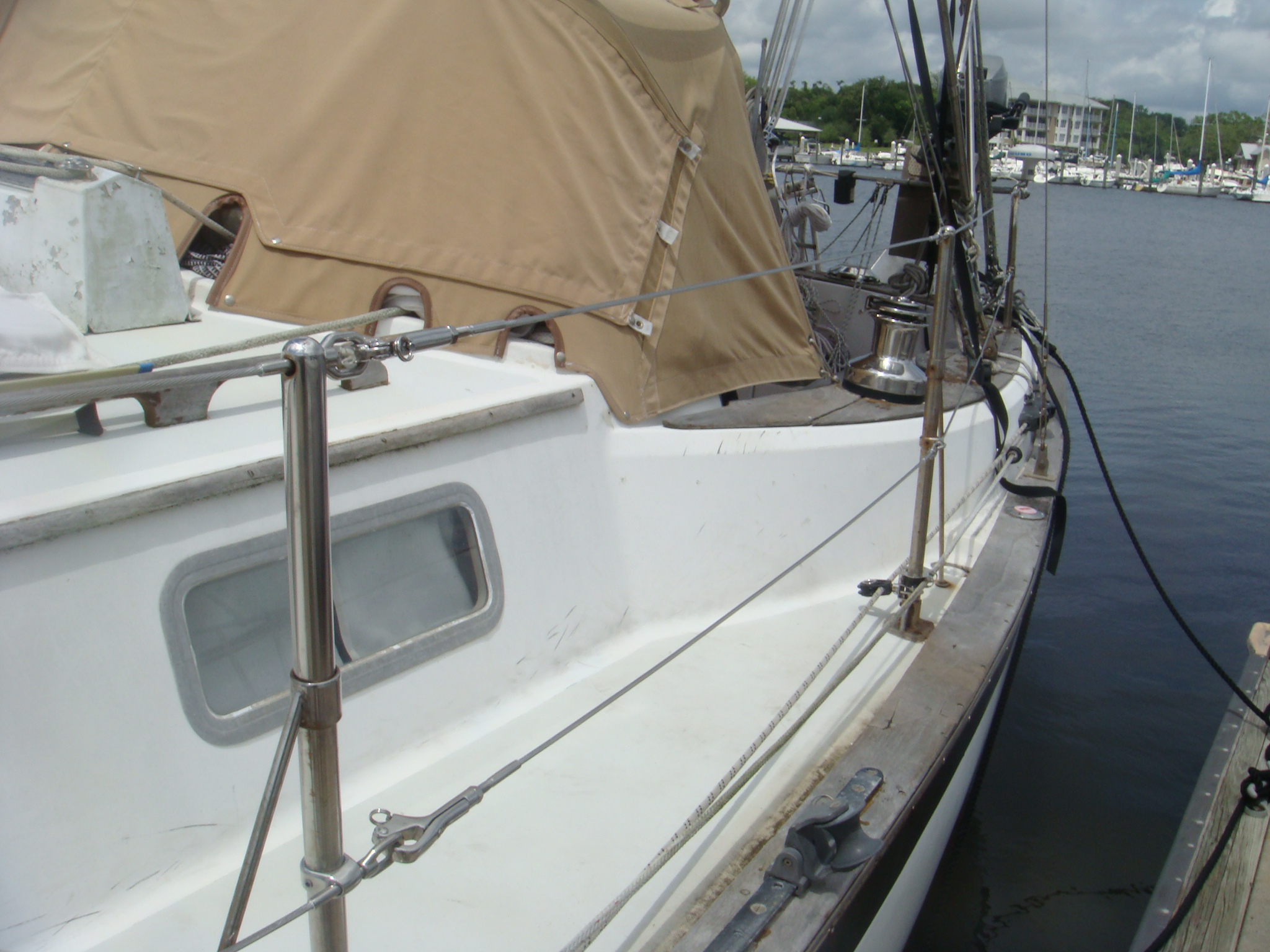 New Lifelines on the Port Side |
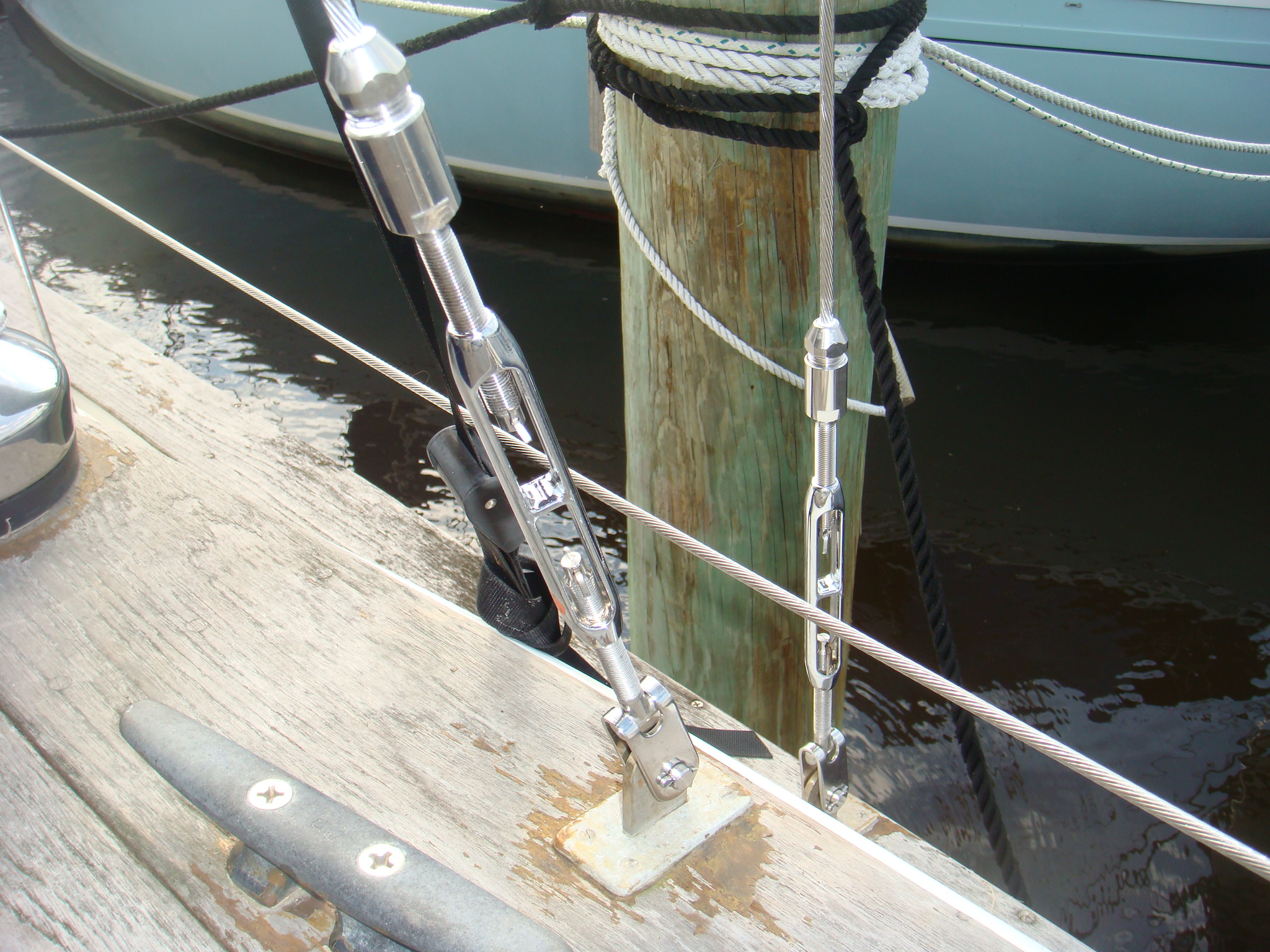
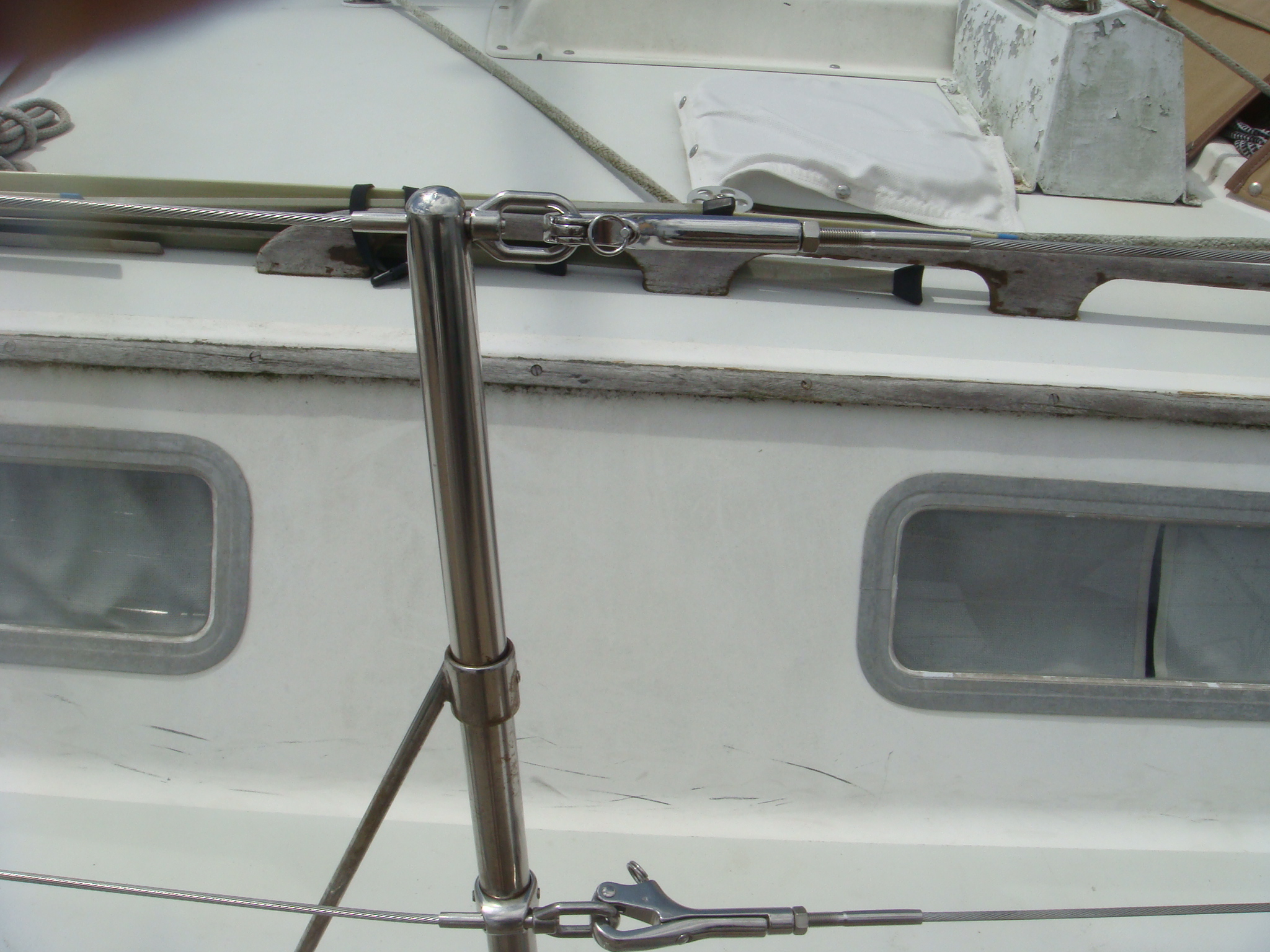 New Pelican Hooks on the Lifeline Gate |
I also elected to not retain the old lifeline fittings and
ordered all new pelican hooks, turnbuckles and connecting rings. I never like the enclosed turnbuckles on the previous lifelines. Those turnbuckles require retaining nuts on the studs to prevent the turnbuckle from loosening, which made making adjustments in the lifeline tension cumbersome. The new lifelines have open body turnbuckles, which I much prefer. |
| I still need ot put cotter pins on the turnbuckle studs, lanyards on the pelican hook shackles and Locktite on the gate eyes, but the life lines are in place. |
 Pelican Hook Still Needs a Lanyard to Make Openning Easier and the Gate Eyes Need to be Secured with Loctite |
| Hatches & Ventilation, 2001-2007 | |
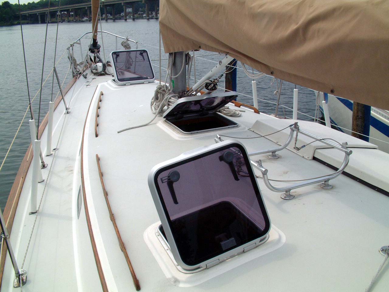 Lewmar Ocean Hatches |
I replaced the three original equipment Bomar hatches with
Lewmar
Ocean Series hatches. I never like those cast Aluminum Bomar hatches. They required support arms to hold the hatch open, which then must be loosened to close the hatch. Two screw-down knobs then had to be tightened to seal the hatch. It typically took several minutes to close the three Bomar Hatches on Sarah. With the Lewmar hatches closing all of the hatches took only a few seconds longer than the time to walk from one hatch to the other. |
| The
main cabin hatch, just aft of the mast had a crack in the frame. I
used the necessity of replacing that hatch as an excuse to replace the other
two as well. I was familiar with the Lewmar hatch design which included self supporting hinges and cam-type dogs. Bomar had a similar hatch, the Seabreeze line, which appeared to be slightly better than the Lewmars. However in their infinite wisdom, the engineers at Bomar decided not to make those hatches as drop-in replacements for the old cast aluminum hatches. The Lewmar hatches used the same size cut-out as the original Bomar hatches. So Lewmar got my business. |
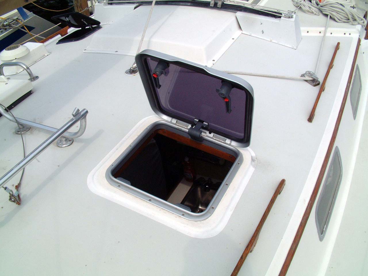 Harch Over Galley |
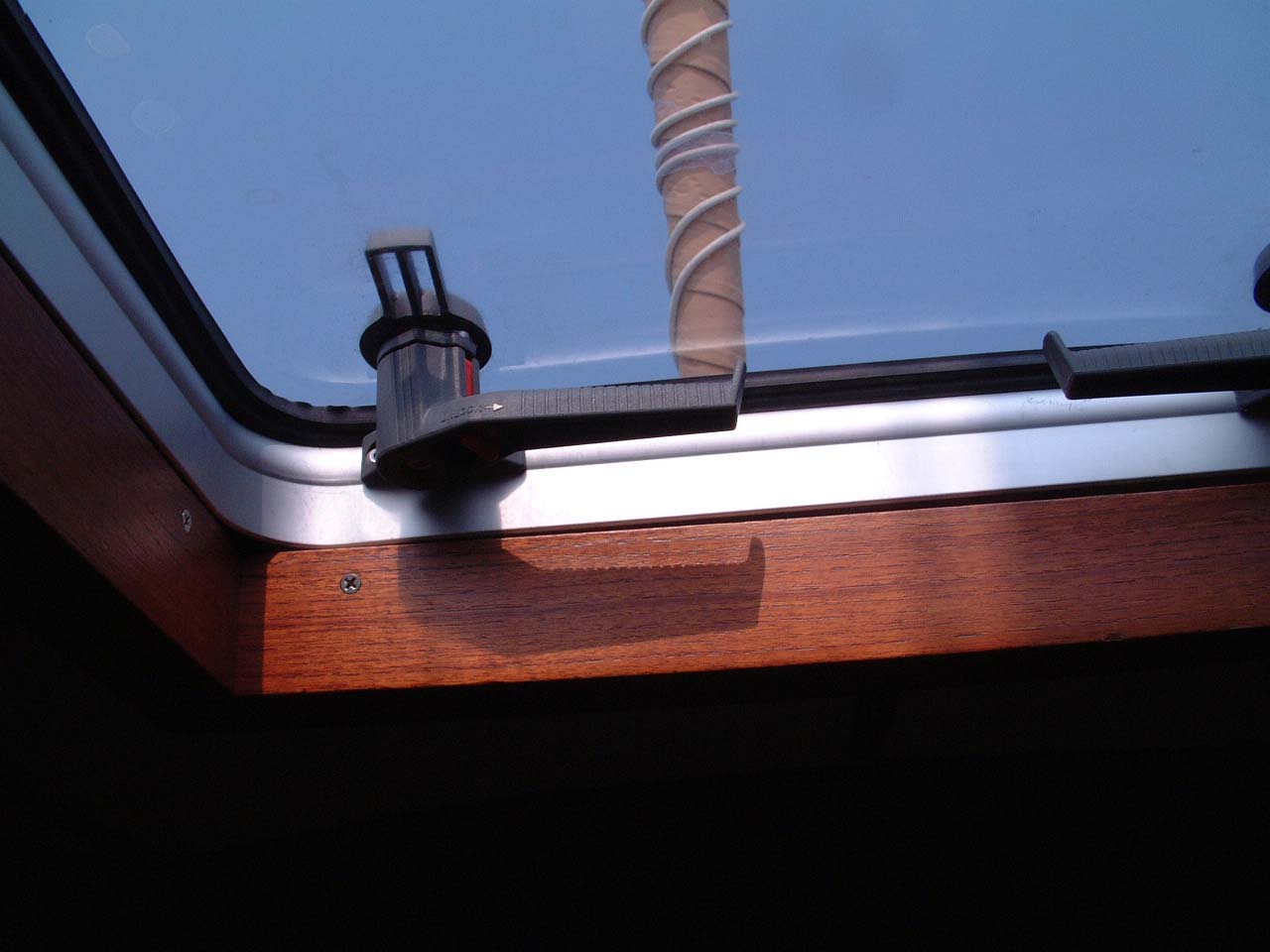 Interior Hatch Trim |
The Lewmar hatches were a nearly perfect fit in the existing cut-out and internal trim. I only had to do a little sanding of the wooden internal hatch frame that is hidden by the trim pieces shown in the picture on the left. |
|
Added
a small deck hatch over the aft cabin berth. This hatch provides the only ventilation to the aft cabin when the companionway hatch is closed. |
 Hatch Over Aft Berth |
 Hatch Over Aft Berth |
It also allows additional light into what is otherwise the darkest cabin on the boat. |
| I replaced the non-closing cowl vents on the transom
deck with
Nicro
Solar Vents which can be sealed in rough weather. These are the
engine room vents. |
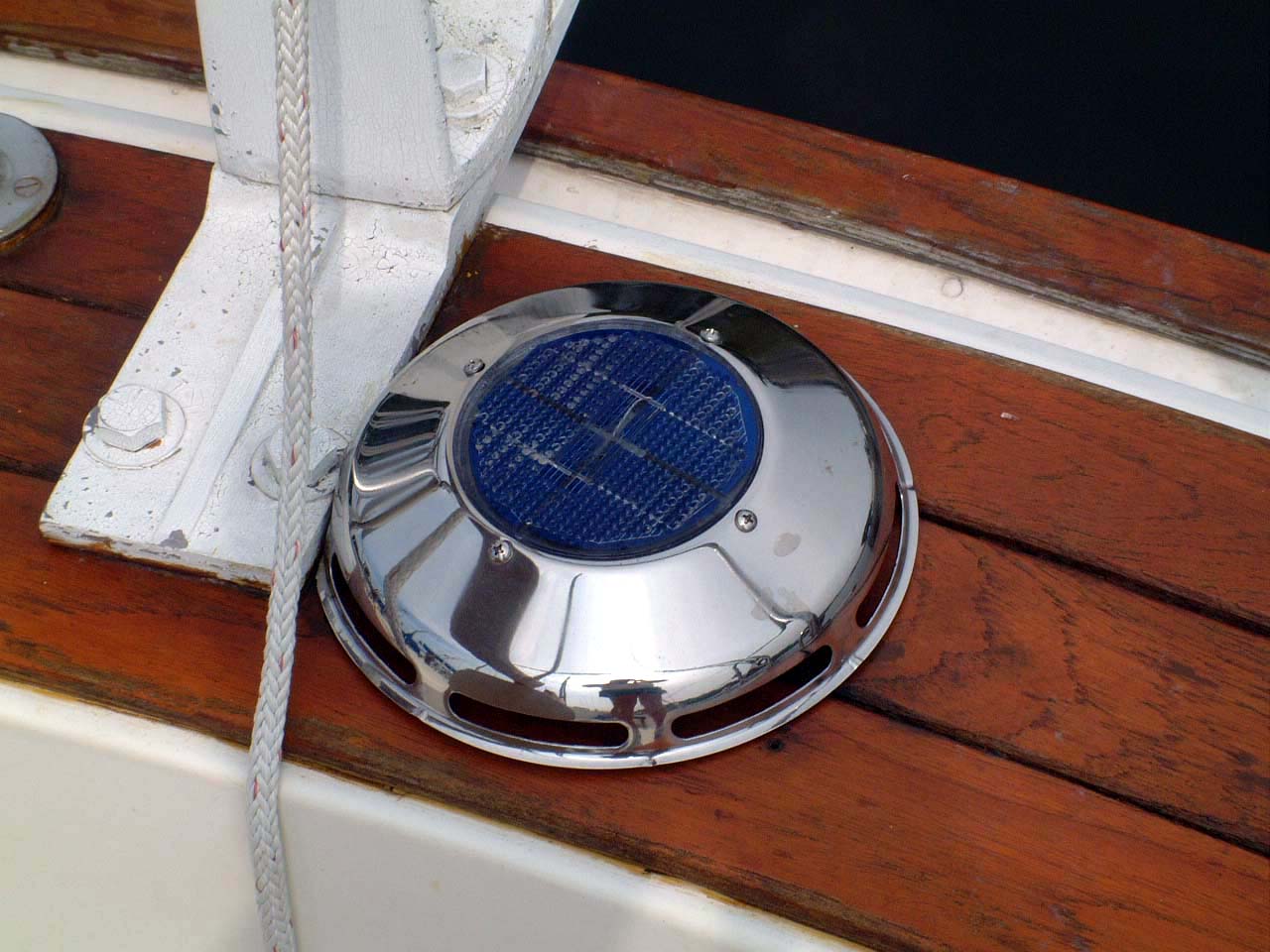 Engine Room Vent |
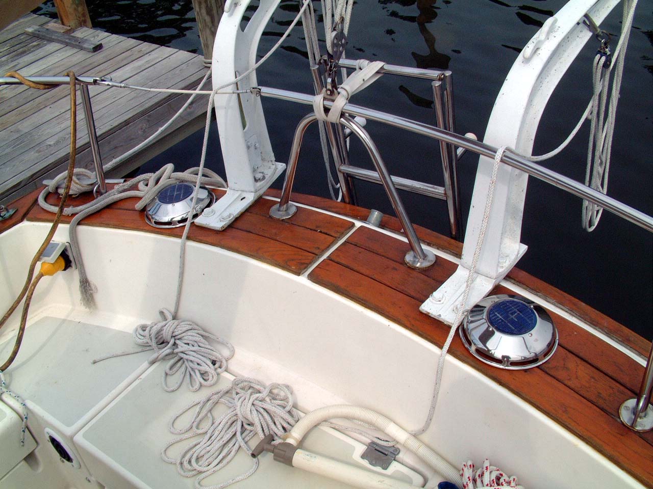 Engine Room Vents |
|
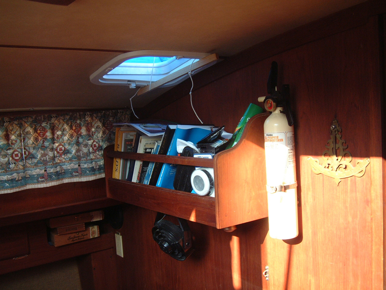
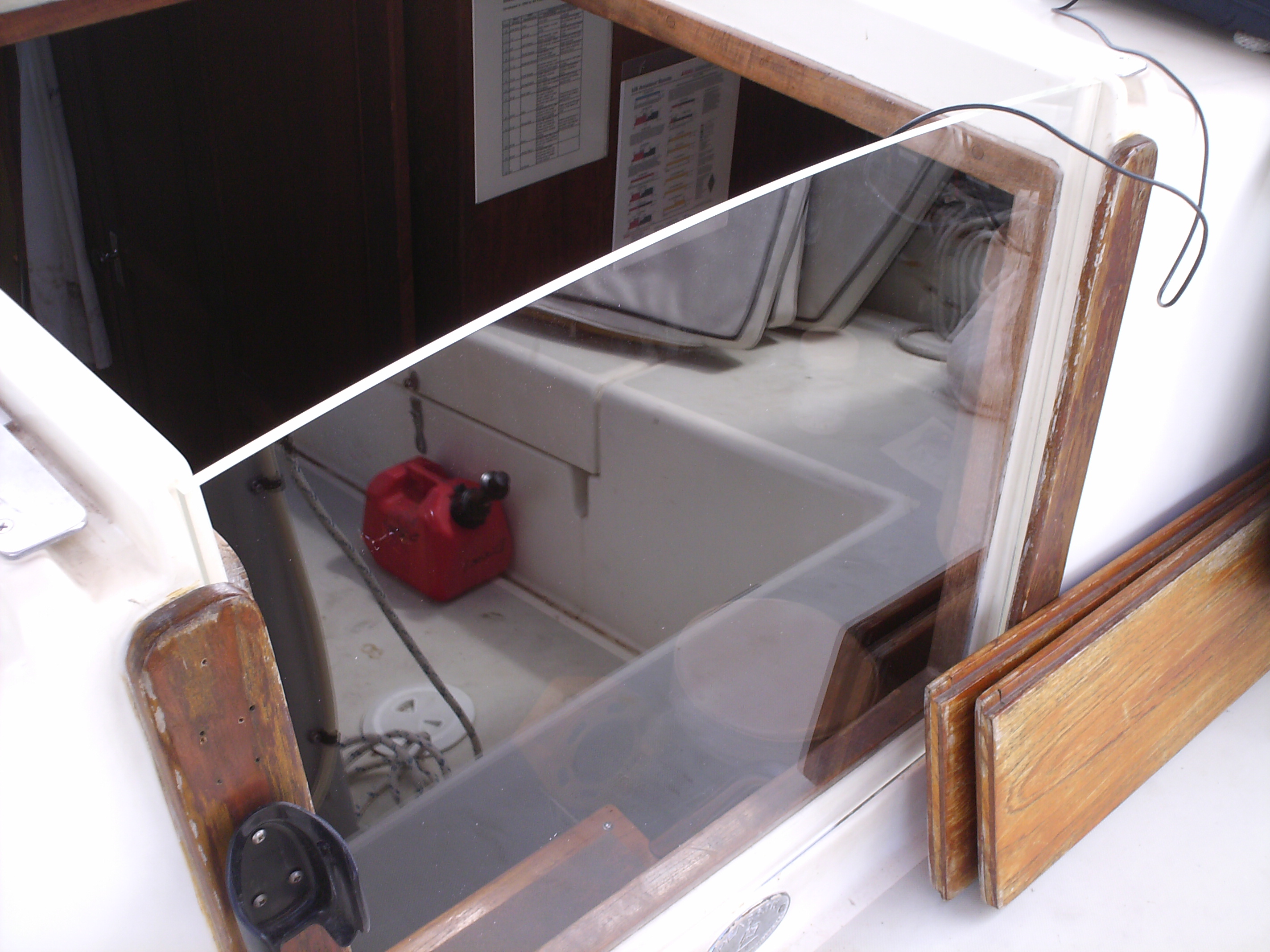
| When I mounted the Raymarine C120 Chartplotter/Radar display on a swing mount in the companionway I knew there was one limitation in that location. When sailing downwind in rain the teak companionway drop boards had to be put in place making the chartplotter and radar display visible only below decks. Just when I might want to scan the area with the radar or check the vessels position I had to go below decks. I lived with this limitation for several years, including one Trans-Altantic sail. Finally just before departing Lagos, PT for the return trip across the Atlantic I fitted a clear perspex drop board to make the C120 display visible from the cockpit even when the hatch is closed. |  View Through the Pespex Hatch Board From Inside the Cabin |
 Perspex Drop Board |
The picture
above is the view through the hatch board from the cabin. I
wonder how many times I'll bash my head into this plastic hatch board
forgetting it is there. On the left is the Perspex hatch board in place. |
| You'll notice the hatch board reflects a lot of light on a sunny day making the C120 hard to see. Of course on a sunny day I don't need the hatch in place. A heavy rain will also make the display difficult to see. Well no solution is perfect. |  C120 Display Behind Perspex Hatch Board |
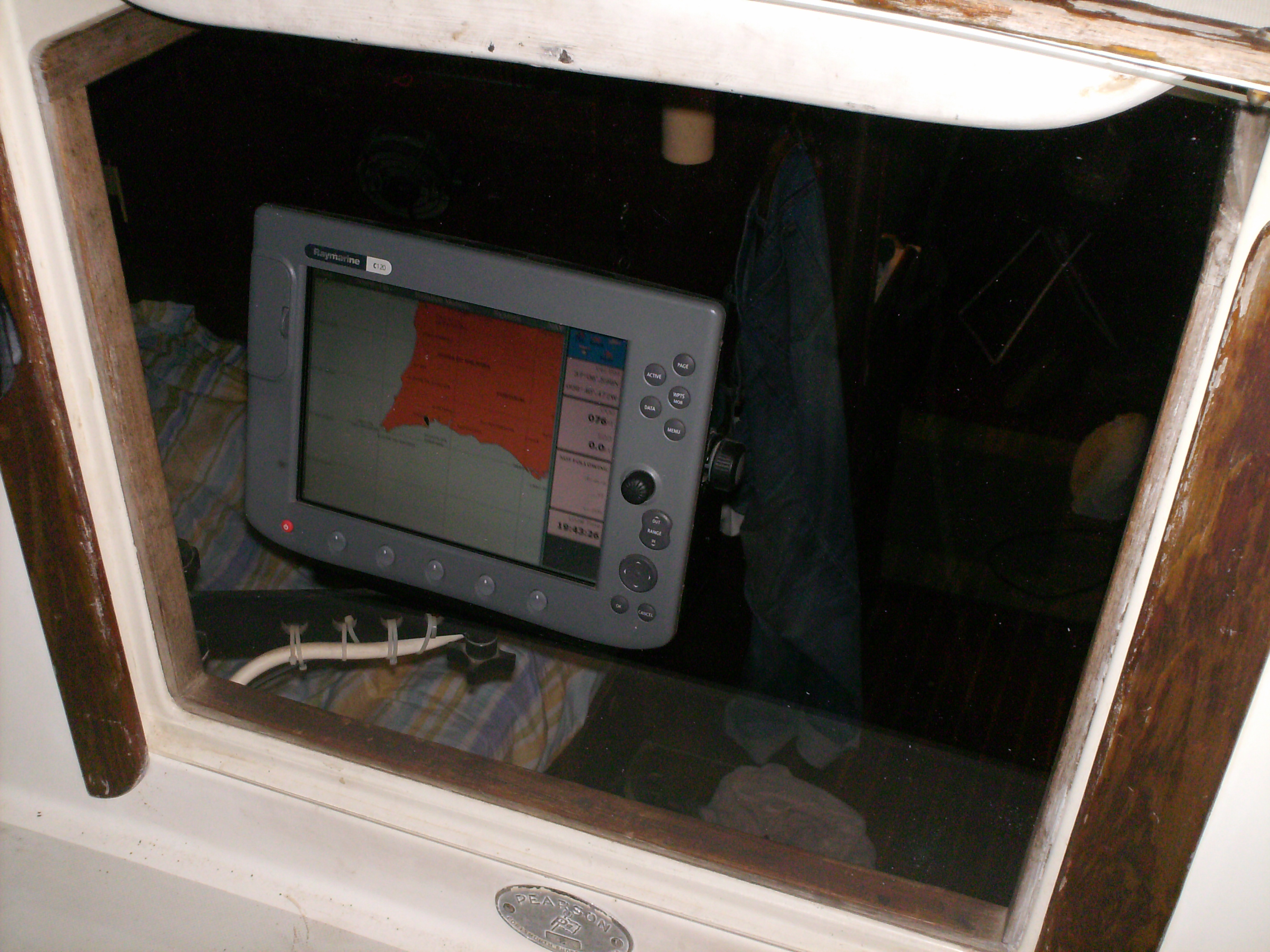 C120 Display Behind Perspex Hatch Board |
On the left the view after dark, even with the reflection of the flash from my cheap digital camera (can't be turned off) the chart plotter is easy to see. |
| Monitor Wind Vane, 2004 | |
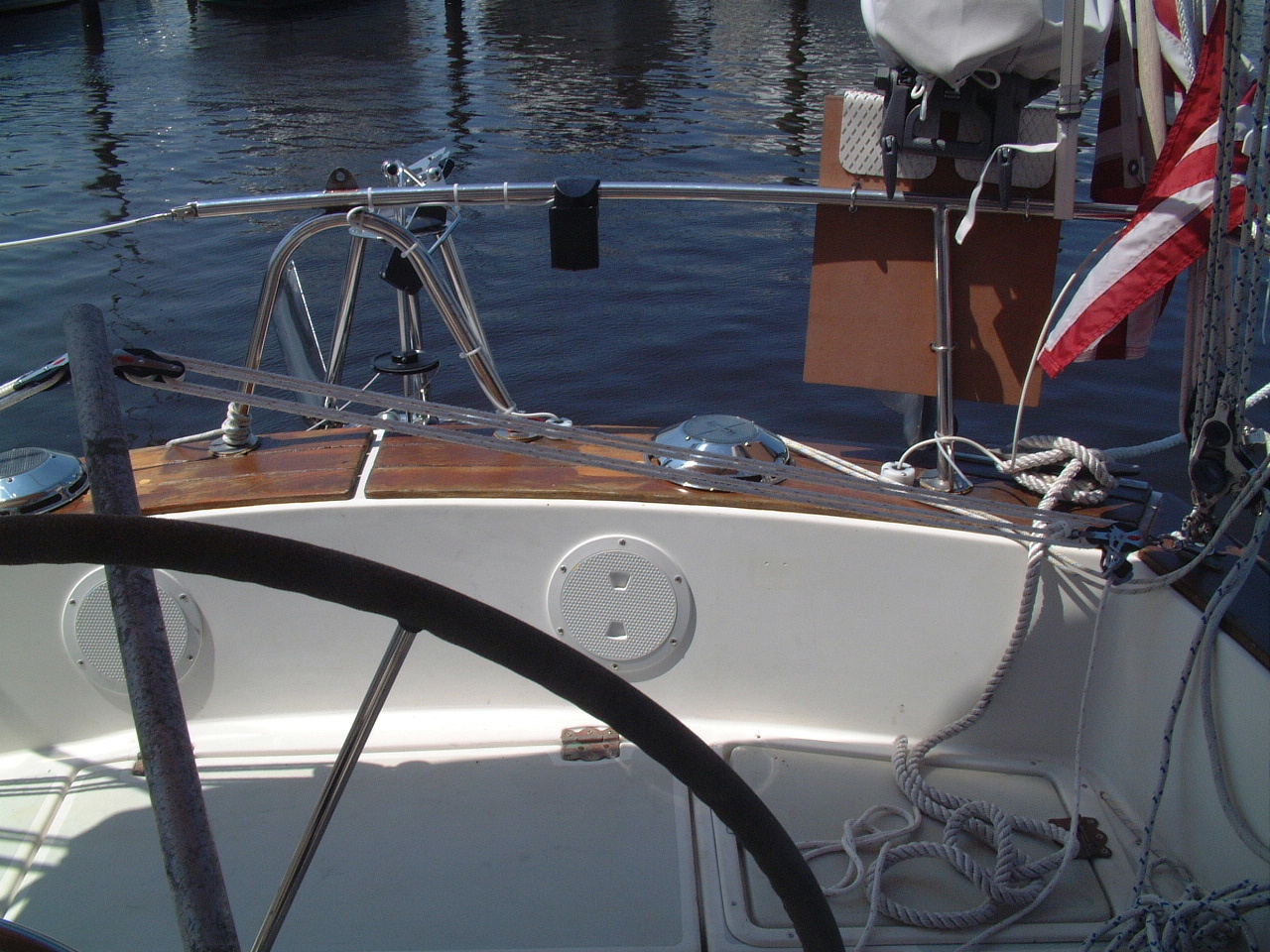
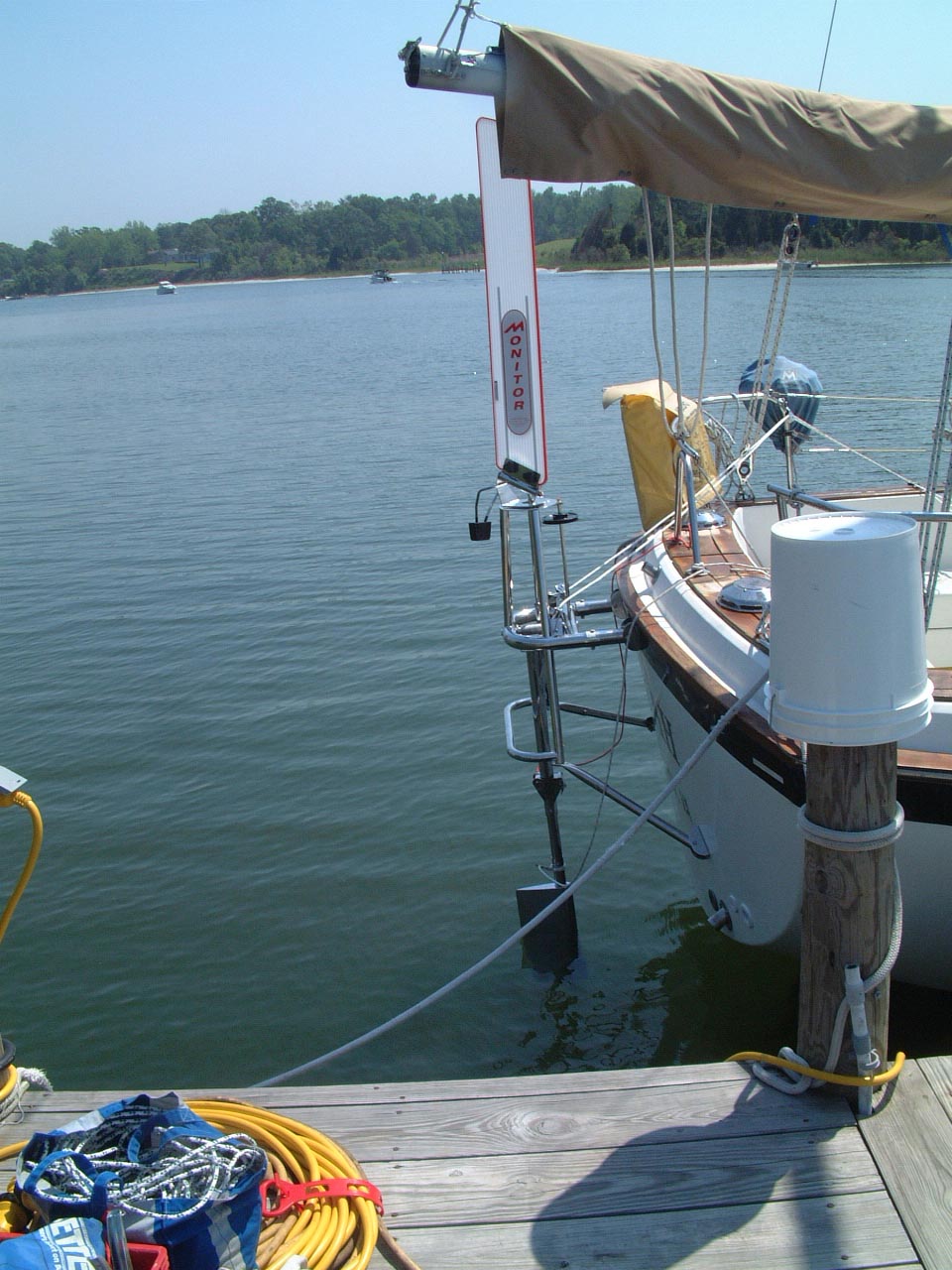 Monitor Wind Vane On Sarah |
Although Sarah's Raymarine 6000+ Autopilot did an excellent job on our Bermuda Cruise and has performed flawlessly since installed, for longer ocean trips I believe wind vane self-steering would be of great benefit. When I purchased Sarah I owned an Aries Wind Vane from my previous boat. I determined that the generator installation would make the installation of the Aries difficult if not impractical. Consequently I sold the Aries and purchased a Monitor. |
| The wind vane precludes storing the dinghy in davits, so I removed the cast aluminum davits that came with Sarah and sold them on eBay. I also removed the swim ladder and may sell that as well. I did install a midships swim ladder the next year (2005) |
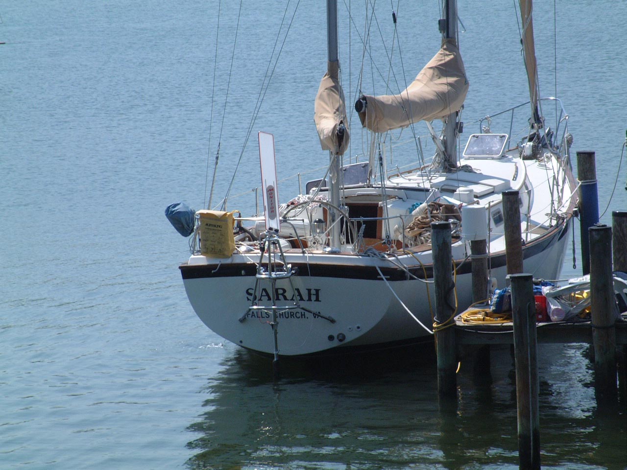 Monitor Wind Vane on Sarah |
 Control Lines for Monitor Windvane |
I
would like to purchase a set of davits that can be removed and stored
during off-shore passages. That way I could use the Monitor Wind Vane
for ocean passages, storing the dinghy on deck. On in-shore passages
(i.e., ICW, French canals, etc.) the Monitor can be removed and stored and
the davits installed so the dinghy will be more immediately available. Well after thirteen years of sailing with the Monitor and the dinghy on deck I still do not have those davits (2017). |
| Re-Running the Monitor Control Line | |
|
The
way I rigged the control lines for the Monitor Windvane worked fine, but it
did have a significant short-coming - I had to disconnect the lines to open
the port cockpit locker. It also meant no-one could sit in the aft,
port quarter of the cockpit when the Monitor was engaged. I lived with those issues for a number of years and two ocean crossings. In 2010 I replaced the original control lines and decided to re-rig them at the same time. I stole the setup shown on the right from Ketch Ya Later. Now the lines are routed from a pair of blocks on the stern rail and another set of blocks beneath the port cockpit locker lid and then directly to the control lines on the wheel. |
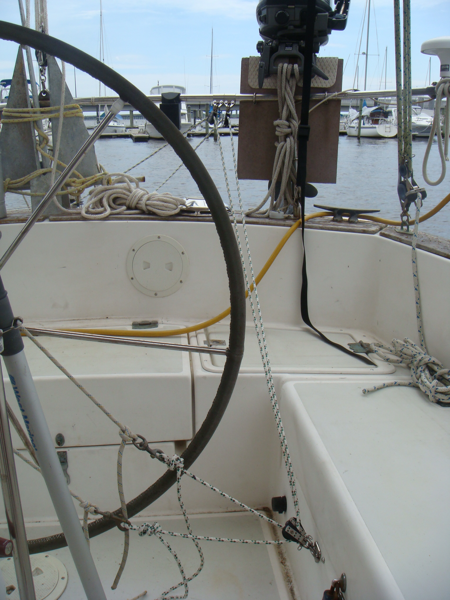 New Control Line Route |
| Emergency Tiller, 2004 | |
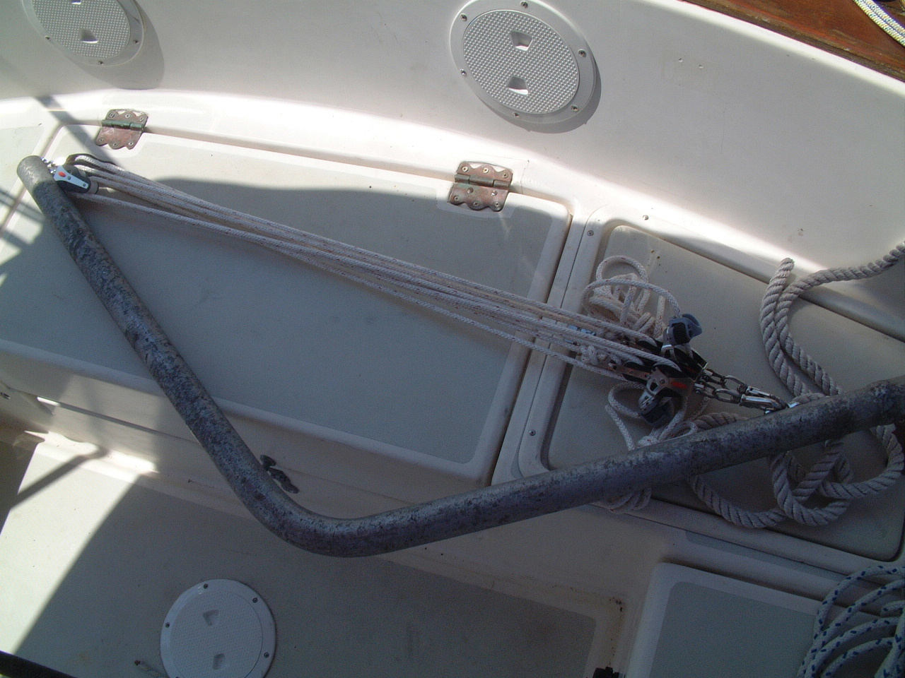 Emergency Tiller with Tackle |
Sarah came equipped with an emergency tiller should the Edson wheel steering
ever fail. The emergency tiller is now actually a second level of backup.
The Raymarine ST6000+ Autopilot I installed in 2000 has its own tiller,
which will allow me to steer the boat should the wheel steering fail.
However the autopilot is a piece of electronics, and a mechanical backup for
both the wheel and autopilot should be equipped for off-shore passages.
The emergency tiller is a 6' piece of 1 1/2" aluminum pipe with an approximate 120 degree bend in the middle (picture on right). |
|
I learned from fellow P424 owner Hal Sutphen that this tiller is a crew
killer if you ever need to deploy it. The P424 rudder is a large, low
aspect "barn door" type hung on a substantial skeg (see the
profile plan for the 424). This is a totally unbalanced rudder, which requires more mechanical advantage than a small tiller such as this can supply. Hal found this out on an offshore passage and had to jury rig some tackle on the tiller to allow he and his crew to steer his boat for more than a few minutes at a time. I borrowed from Hal's experience and set up two tackles on the tiller to allow a helmsperson to move and lock the tiller with little effort. Hopefully we never have to find out if this system really works. The picture on right shows the deck plate over the rudder post removed and the emergency tiller fitted to the rudder head. |
 Emergency Tiller Installed on Rudder Post |
 Emergency Tiller Tackle |
The picture on the left shows the tackles deployed to the running backstay padeyes. The picture below shows the tiller hard over to starboard for a turn to starboard. Since the tiller faces aft it works the opposite of a standard tiller. |
 Emergency Tiller Hard Over to Starboard |
|
| Stern Light, 2004 | |
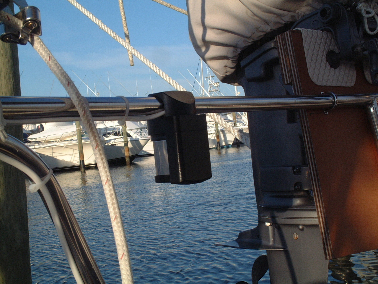
| It may not be clear in the pictures above, but it was apparent to me once the Monitor was installed that it would totally obscure the stern running light. This light is original Pearson equipment installed flush in the transom about 6" below the deck. I ignored that issue until I had to have Sarah surveyed for my off-shore insurance and the surveyor wrote that up as an issue that must be corrected. | |
| The simple fix was to install an Aqua Signal Series 25 stern light on the stern pulpit outboard of the Monitor. This was not an elegant installation as I ran the wires outside of the pulpit tubing, but I think it is sufficiently robust. The Series 25 lights are designated by Aqua Signal for boats < 12 meters in length. Sarah is 12.7 meters in length. |
 Stern Light Mounted on Rail |
| I don't think the Aqua Signal specifications reflect any formal international requirements. In any case I did not want to have to install a series 40 light. Not only is it more expensive and draws more power, it also puts more light into the cockpit hurting the night vision of the watch at night. Tim Kirkpatrick's Sweden Yacht 38, on which I raced twice to Bermuda, had a factory installed series 40 light on the rail and it was really a distraction when sailing at night. In any case the series 25 Aqua Signal light is many times more bright than the 1970s vintage Perko light it replaced. So I feel I have enhanced Sarah's running light configuration even if I have not gone with the light most surveyors would specify. | |
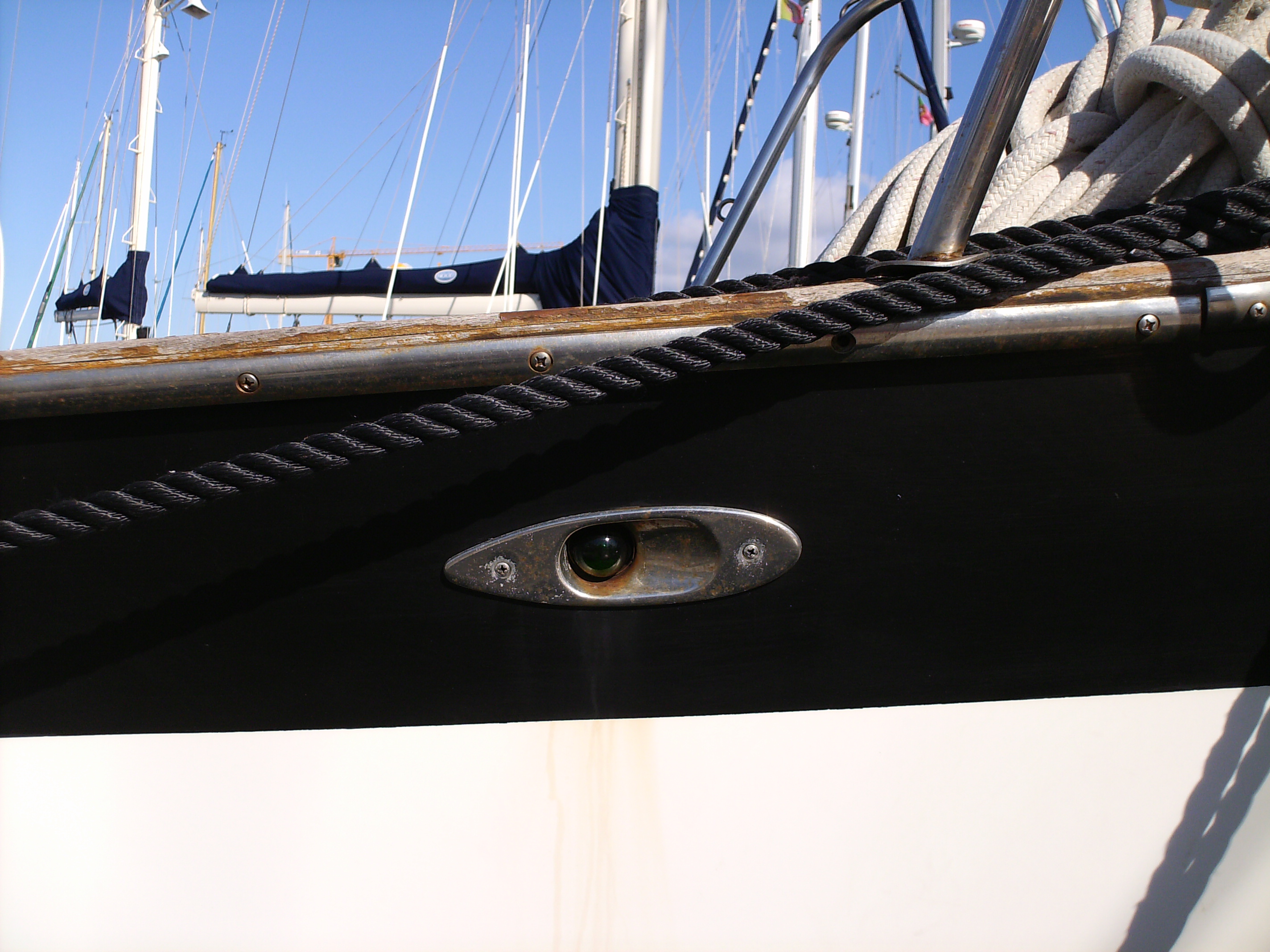
| Bow Running Lights and Bow Rail Re-bed, 2007 | |
 Port Running Light |
The original bow running lights appear to be standard Perko fixtures screwed into the hull just below the cap rail on each side of the bow. This was the standard arrangement back in the 1970s, but it had a number of deficiencies. The most important deficiency is that the lights were not very visible when under sail. The lights are low on the boat, within 5' of the water and when the boat heels under sail one of the lights is pointing down at the sea and the other up toward the sky. The back of the fixtures were not sealed and received a lot of moisture from the anchor locker. |
| Before we left Cascais, PT for Gibraltar in April, 2006 we noticed that the port bow light (picture on the left, above) was not working. Martin Morgan got it working before we left, but we knew the fixture needed replacement. That summer I didn't do a lot of night time sailing, but every time I did I had to go forward and tweak the light to get it working. I guess those old Perko light fixtures are still available, but if I was going to replace it I wanted to move the lights from the hull to the bow rail where they would be more visible. |
 Starboard Running Light |
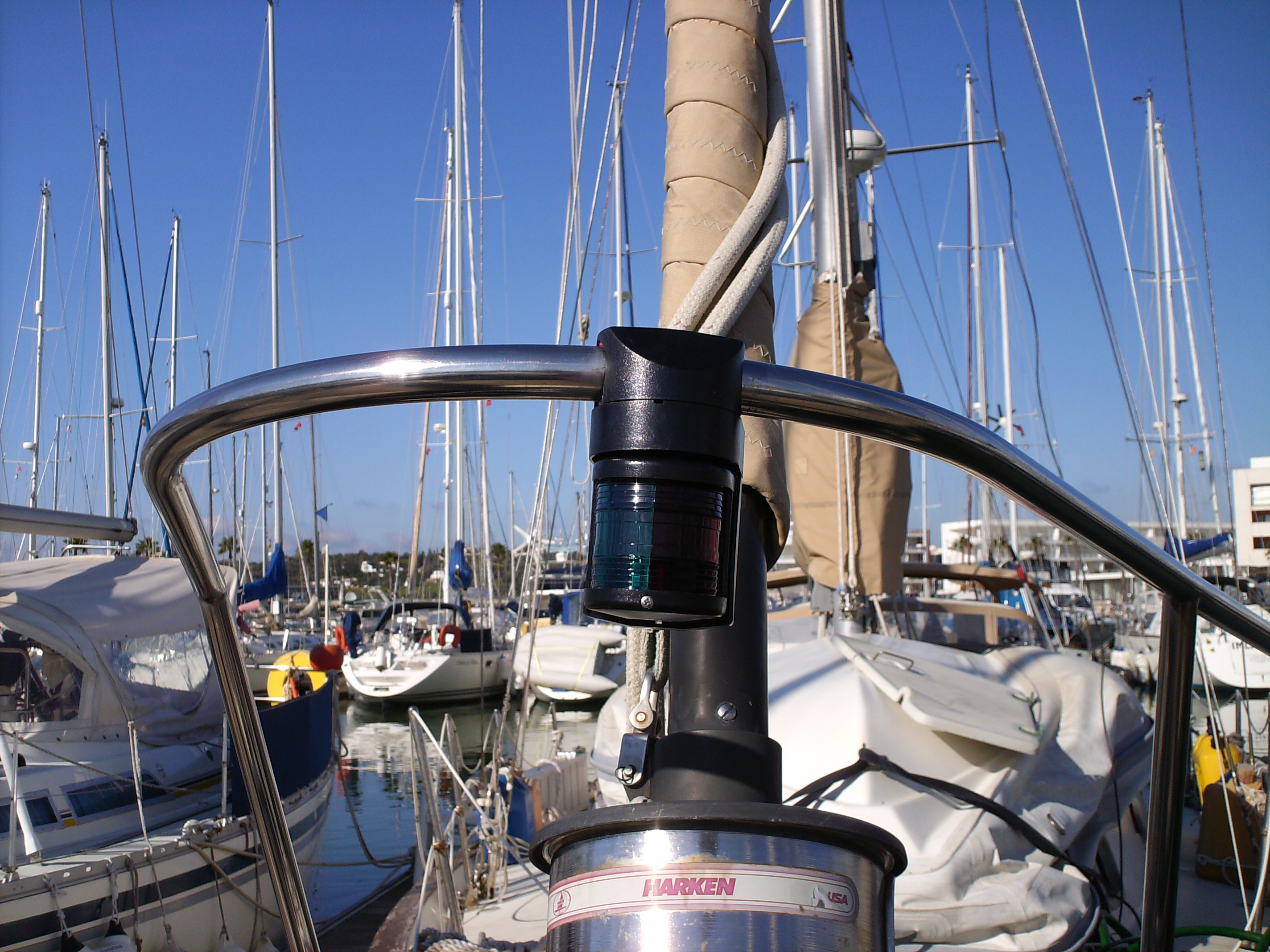
 Aqua Signal Bi-Color Light |
I selected a bi-color light from Aqua Signal to match the stern light installed before my departure from Florida. This is a Series 25 light fixture, and like the stern light is specified for yachts under 12M. The Series 40 light fixture is much larger and draws a lot more current so I stayed with the Series 25. Even if it is not as bright as the Series 40 light it is a marked improvement over the Perko lights. |
|
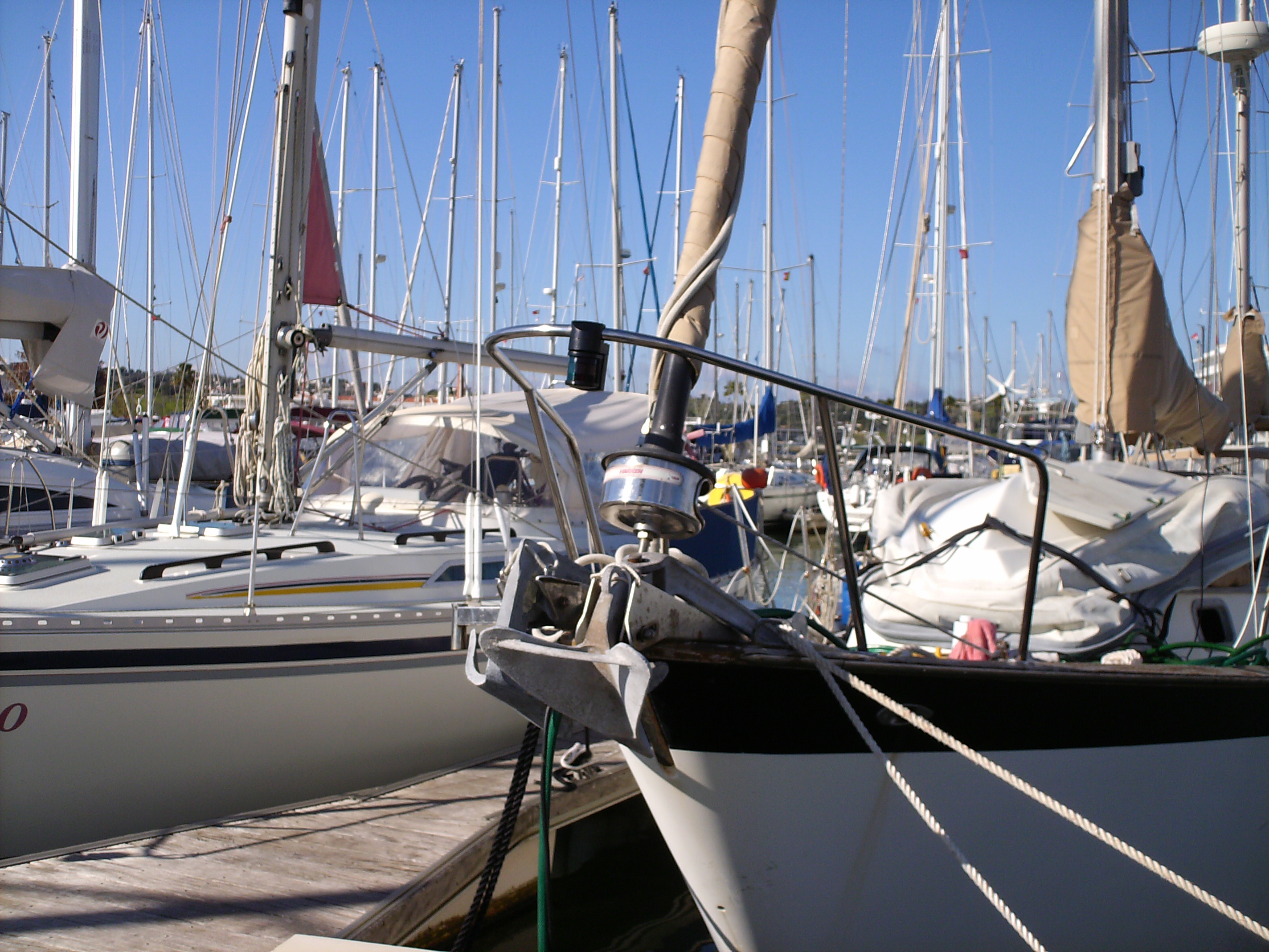
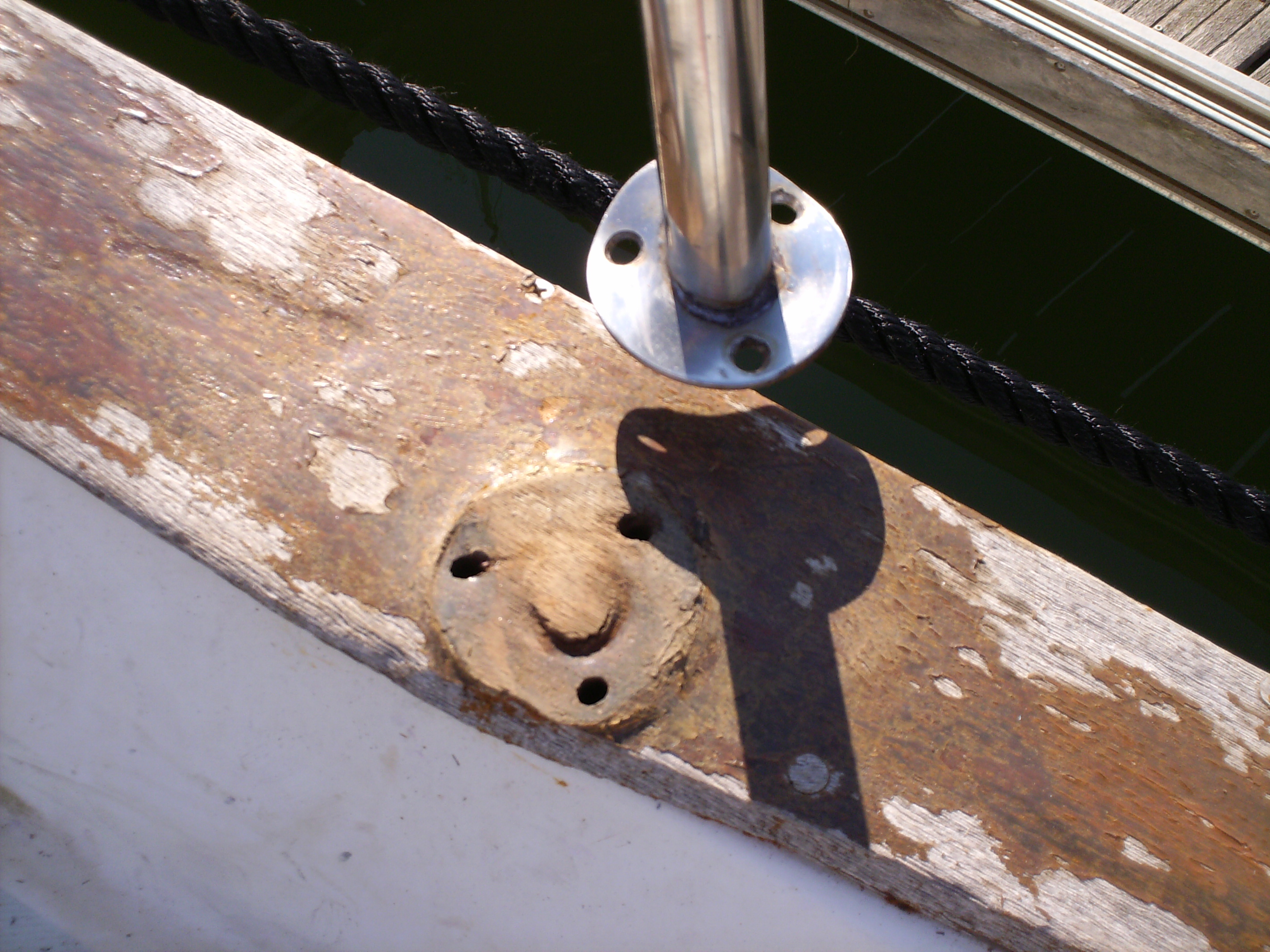
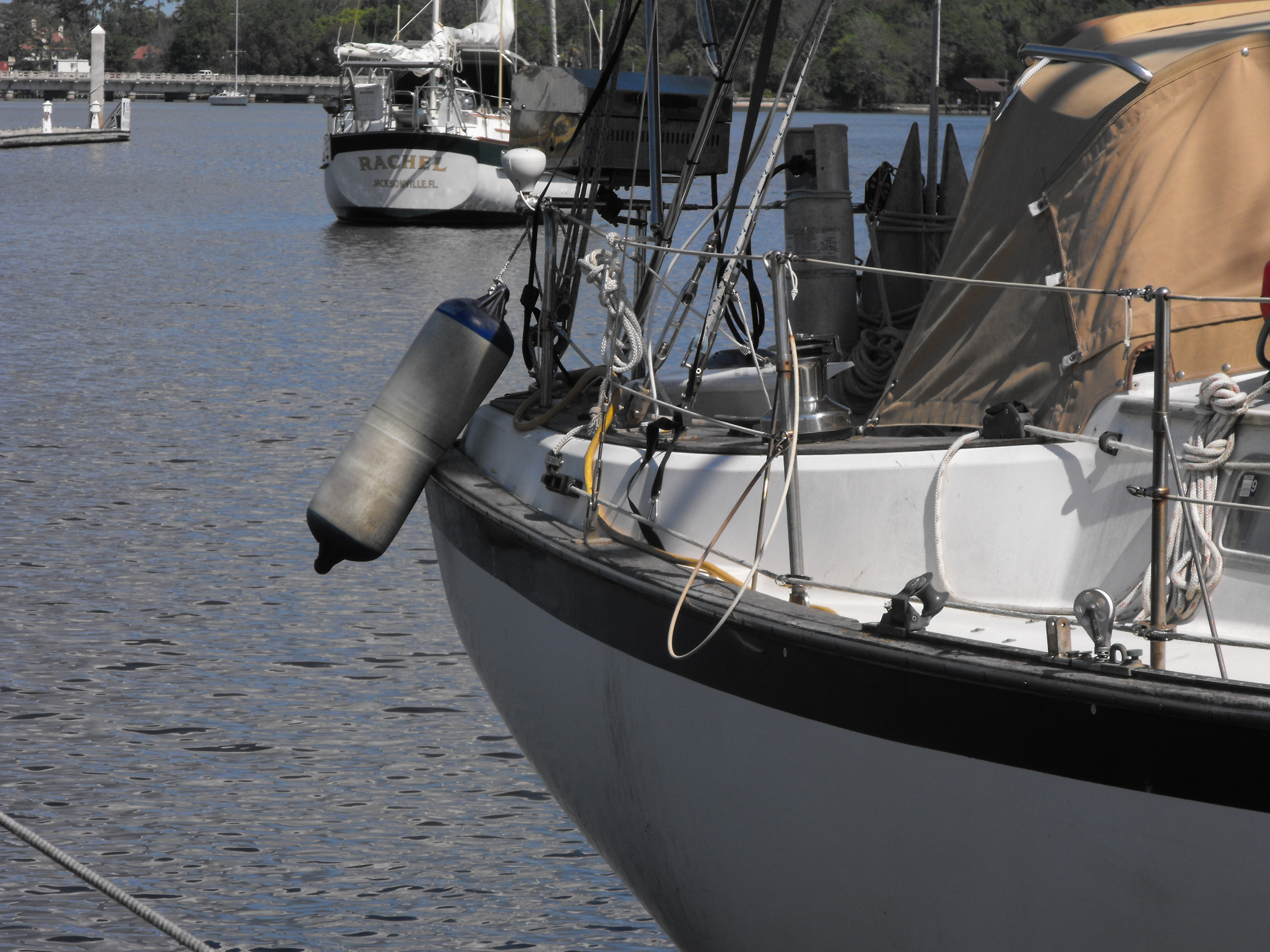
I used the same rail mount bracket for the bow running light as as I used for the stern light. The only drawback to this mount is that the light is vulnerable to being struck by the shaft of the anchor when it is being deployed or brought back on board. As long as I'm careful this shouldn't be a problem. I may see if I can get a short piece of tubing bent around the light and attached to the rail. That would provide some protection for the light if I lost control of the anchor. I considered mounting the light above the rail, but decided that would have made it very vulnerable to being caught by the Genoa or the Genoa sheets and ripped of the mount. Time will tell if this was a good decision. |
|
 Bow Pulpit Bent |
While I was preparing to mount the new running light I first noticed that the bow rail has been bent significantly to Starboard. I never noticed this until I fitted the light at the center of the arc of the rail and discovered that position was directly over the starboard anchor roller. I have no recollection of hitting anything with the bow rail, at least not with sufficient force to bend it to this degree. You can see that I had to mount the new light on the port side of the rail to get the light reasonably close to the centerline of the boat. |
|
Looking at the rail more closely I noticed that each of the stanchion bases were severely deformed. It appeared that the rail came into contact with some other object with sufficient force to nearly rip the stanchions off the through-bolts. Shades of my crushing the stern rail on departure from Ft. Pierce, FL 1 1/2 years ago. However, now that I was looking closely at the bow rail I could see that the stanchion bases were so badly bent that there was natural path for water to flow under the base. If the machine screws securing the stanchion to the deck were not properly bedded water could easily seep into the hull-deck flange joint and flow between the flanges until it hit a flange screw that provided a path into the interior of the boat. |
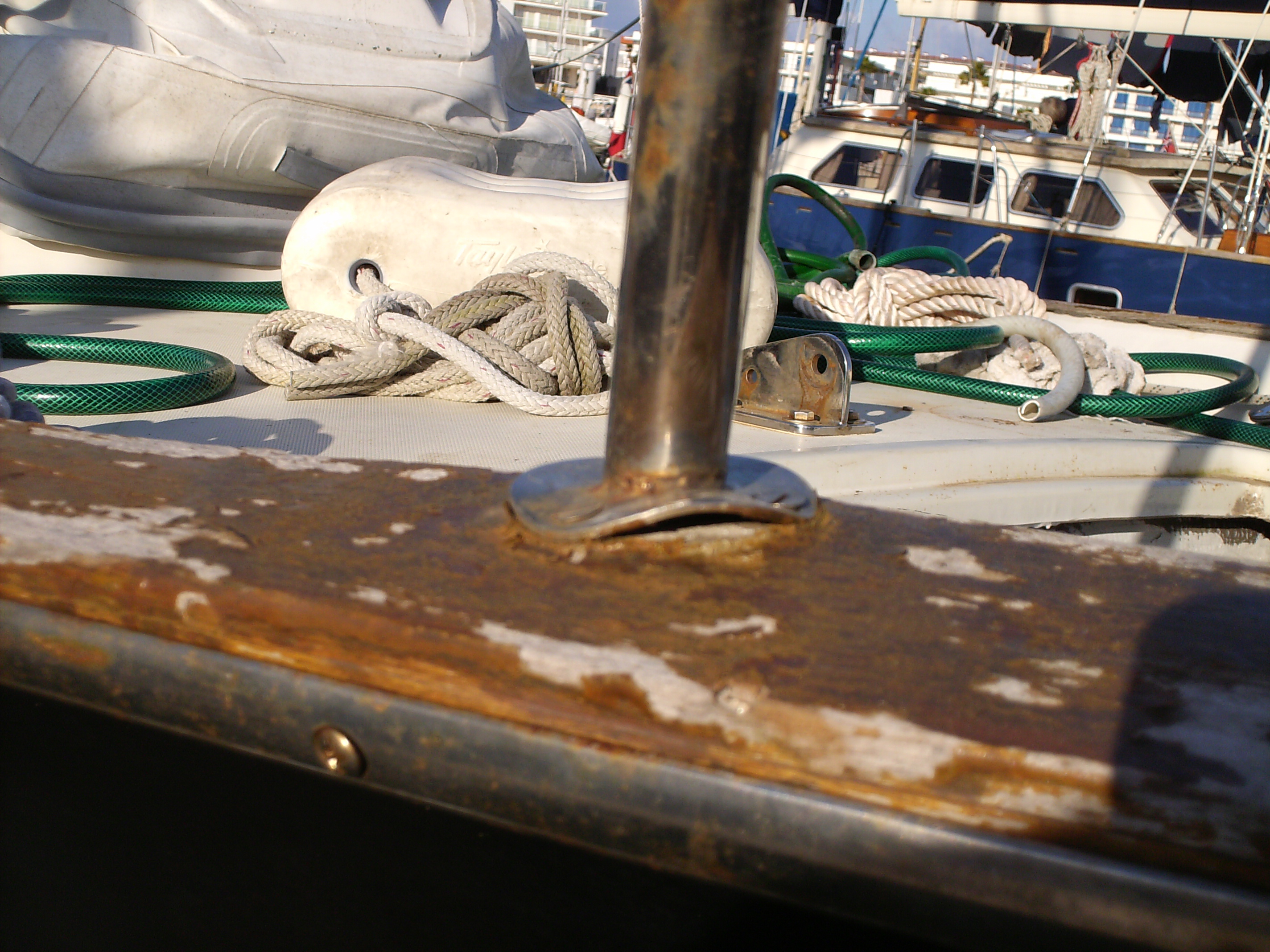 Bent Stanchion Base |
|
In the spring of 2006 I noticed that the vinyl lining in one of the
lockers in the forward cabin was moist. I had looked for the
source of the leak, but I couldn't pin point any one source. This
fall about the time I was preparing to install the new running light I
was also doing a complete cleaning of all of the lockers and cabin wood
work on Sarah. Then I noticed that that lining in this locker was
severely mildewed. So much so that I decided not to try to clean
it, but removed the vinyl lining. Over the next several weeks we
had almost daily rain showers in Lagos, PT where Sarah was berthed.
Now I could see how much water was leaking into this locker and it was a
lot. Without the foam in the lining to absorb the water it
collected in small puddles in the locker. These puddles were less
than a table spoon of water, but that is a lot of water to come through
the deck. Now I could also see where the water was entering the
locker - through the self-tapping screws used to clamp the hull-deck
flanges. These screws are covered by the teak cap rail and I did
not believe that much water could come through the cap rail. The
cap rail was worn from 28 years of sanding and scrapping the teak and
heads of some of the screws hold the rail to the deck are now exposed,
but I just couldn't see how that much water could seep through those
screws into the deck and then into the locker. Up to this point I had debated with myself whether to run the wire for the new running light on the outside of the rail (as I did for the stern light) or run it inside the rail. That later option is a much better choice, but it would require removing the bow rail from the deck to drill a hole for the wire. Until I realized the rail might be the source of my leak I was strongly inclined to just run the wire outside the rail. Since I now intended to re-bed the rail stanchions running the wire inside the rail was the only choice. |
|
| For a number of reasons I decided to attack the installation and re-bedding without completely removing the rail. I assumed the deforming of the rail was still putting a lot of pressure on the stanchions and if I removed all of the through bolts the rail would spring significantly out of alignment with the current mountings. In stead I elected to work on one side at a time. The first side I attacked was the Port side, which is where I intended run the electrical wires for the running light. After the wire had been run, the light installed and checked out I would re-bed the stanchions on that side and then start work on the starboard stanchions. The port side is also the side of my locker leak. | |
 Starboard Stanchion Base |
When I removed the Port stanchions from the deck I could not detect the presence of any bedding compound on the deck. The P.O. may have removed the rail after it was bent and attempted to put it back into shape in a machine shop or home workshop. When the rail was re-attached the P.O. may have thought it a temporary installation or just figured any water leaking under the stanchion would just go into the anchor locker and overboard. The picture on the left is of the starboard aft stanchion. |
| After installing the bi-color running light on the rail, running the wire through the rail, connecting it to the existing running light circuit (eliminating the old lights from that circuit), verifying the light work I was ready to re-install the port-side stanchions. For that task I replaced the flat-head machine screws with round heads. I've never understood the reasoning behind using recessed screw head in deck plates. It does provide a flush appearance, but it severely weakens the holding power of the machine screw when a strong upward force is applied (such as what happened when I crushed the stern rail). | |
| Re-bedding the stanchions was relatively easy. It is easier to fasten the through bolts than it was to get them off. I initially just hand tightened the nuts, and then 24 hours later tightened them fully. After that I re-installed the hatch over the anchor well, which I had removed to allow me access to both the bolt heads on the cap rail and the nuts under the deck in the anchor well. Finally I re-attached the lifelines to the bow pulpit and tensioned them. |
 Stanchion Base Re-Bedded |
| This job took a lot longer than I thought. However it does appear to have solved my deck leak. One year later (March, 2008) and no water has appeared in that locker. | |
| Boarding Ladder, 2004 | |
| In addition to obscuring the stern light, the Monitor installation required the removal of the boarding ladder on the transom. This was a small loss as the ladder was poorly designed and installed. Further the Pearson 424 transom is very thin fiberglass and it should have been reinforced in the area where the ladder was installed. I was glad to get this ladder off the boat in general and off the transom in particular. | |
 Tops-In_Quality Boarding Ladder |
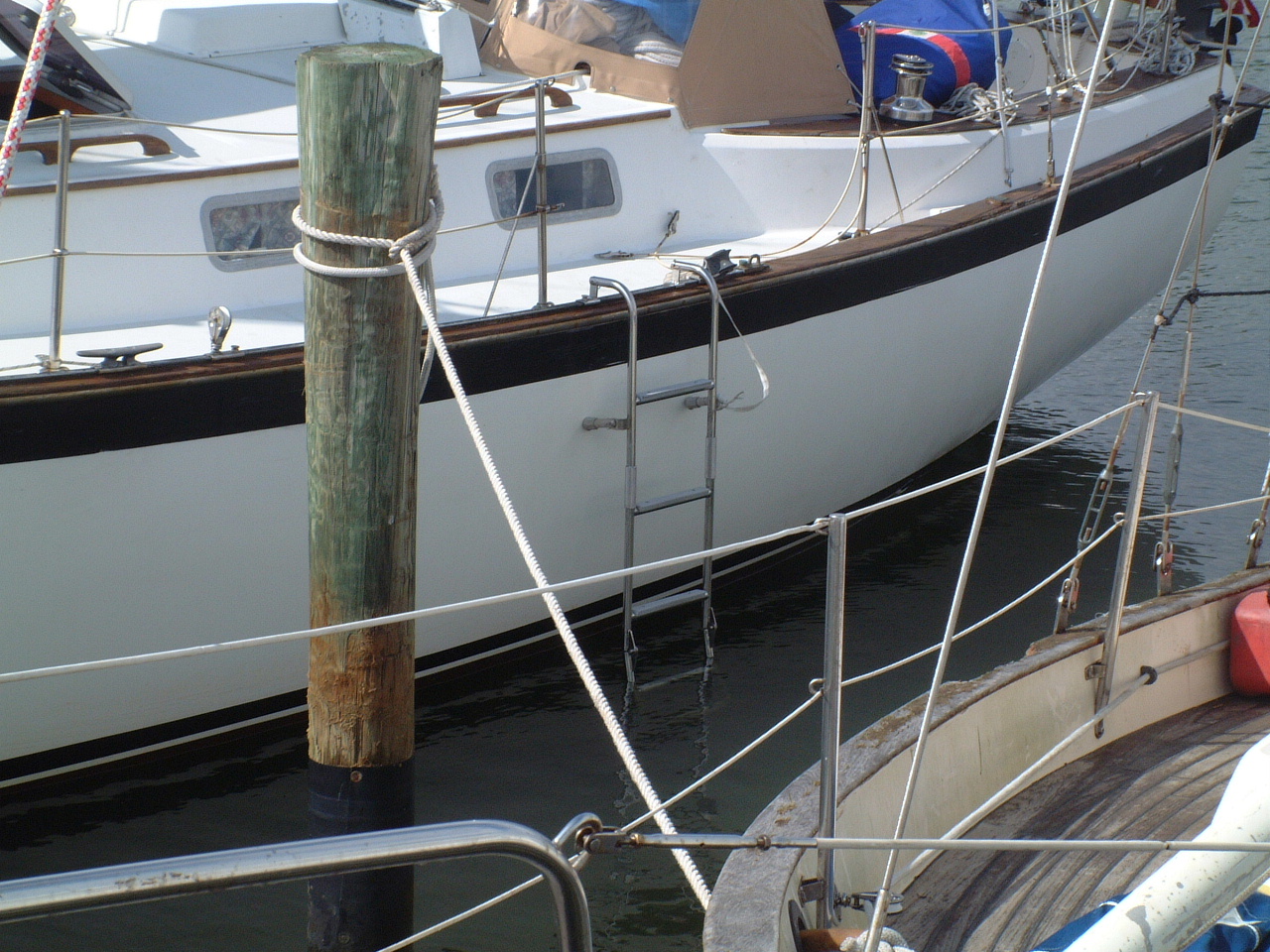
However, I still needed a ladder to get on and off the boat when not tied to a dock. I elected to go with a amidships ladder attached to slides on the Genoa track. I purchased the ladder from Tops-In-Quality, shown on the left. |
| The ladder will have to be removed and stored on deck or in a locker when under sail as it will likely foul the Genoa sheets. I also have a fiberglass step that can be suspended from the same track slides. This step is sufficient for boarding Sarah from a dinghy or water taxi, but it is not sufficient for boarding from the water. |
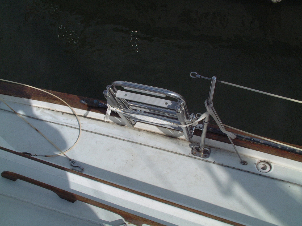 Boarding Ladder Folded |
| Passerelle, 2006 | |
|
In
much of Europe (and almost all of the Mediterranean) most marinas do not have floating docks or finger piers, but rather
offer what are called Mediterranean Moorings or Med-Style Moorings. This is
simply a concrete dock to which the boat is moored with a couple of lines
ashore and the use of the boat's anchor to hold it off the dock. Most
of the marinas in the Western Med are also equiped with submerged mooring anchors (normally
concrete blocks) set the appropriate distance off the dock for the size boat
to be accommodated, eliminating the need to use the boat's anchor. Because the rudder on
Sarah is very near the transom and could strike bottom in a shallow berth
and I have the Monitor Wind Vance mounted on the transom, I dock Sarah
bow-in. This means I secure the mooring line to one of the cleats on
Sarah's stern to hold the boat off the dock and use two bow lines to pull
her back toward the dock and keep the bow from swinging side to side. This arrangement is initially awkward for most North American sailors who are used to tying off to pilings and finger piers. It does allow the marina to pack the greatest number of boats into a given dock space, which I assume is the reason for its popularity. Once I had secured Sarah in this manner a couple of times I have found it is actually quite easy (at least where the moorings are provided by the marina). The only problem it presents is how to get on and off the boat with no pier or pontoon along side. Initially I just pulled Sarah's bow in close to the dock so I could use the crown of the Chinese CQR anchor as a step to climb on and off. This worked OK, except at very high tide, when it was difficult to get my foot onto the anchor crown while standing on the dock. A person shorter than I would have found it very difficult. |
|
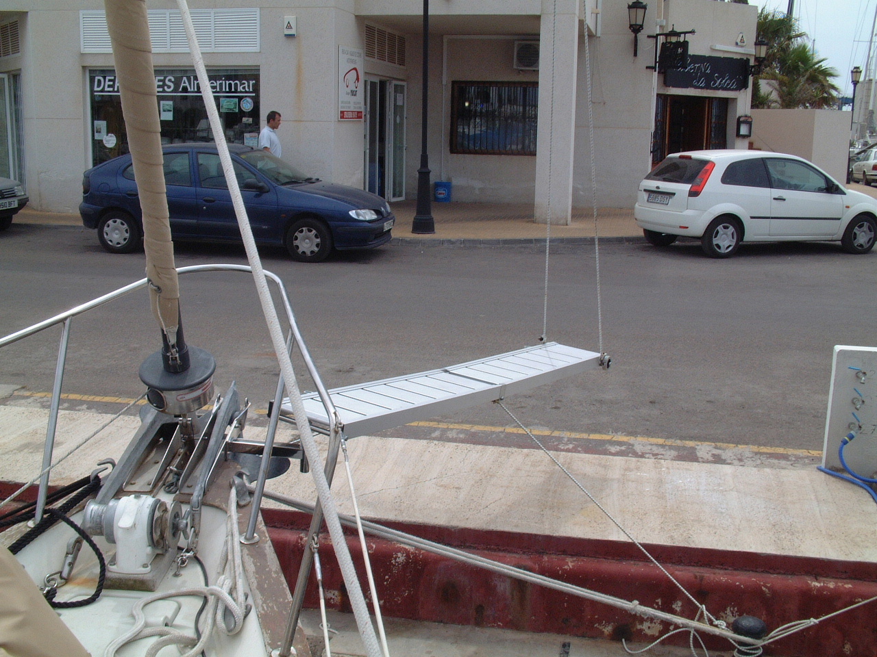
| The common practice is to use a Passerelle or gang plank for this purpose. When I was in Gibraltar I purchased a folding aluminum Passerelle from Sheppard's Chandlery. Then I discovered there was no effective way to secure the Passerelle to Sarah's bow. In order to use the new Passerelle I either had to moor Sarah stern in or fabricate a way to mount the Passerelle on the bow. |
 Passarelle on Sarah's Bow |
| For the first two weeks I tried several approaches to mounting the Passerelle, but all were totally unsatisfactory. Walking the docks at each of the Marinas I stopped in at this time I noticed that many of the bow in boats had a stainless steel mount for their Passerelle bolted to the side of their anchor roller. That looked like the best solution for Sarah, but I had to find a metal shop that knew how to fabricate such a mounting. | |
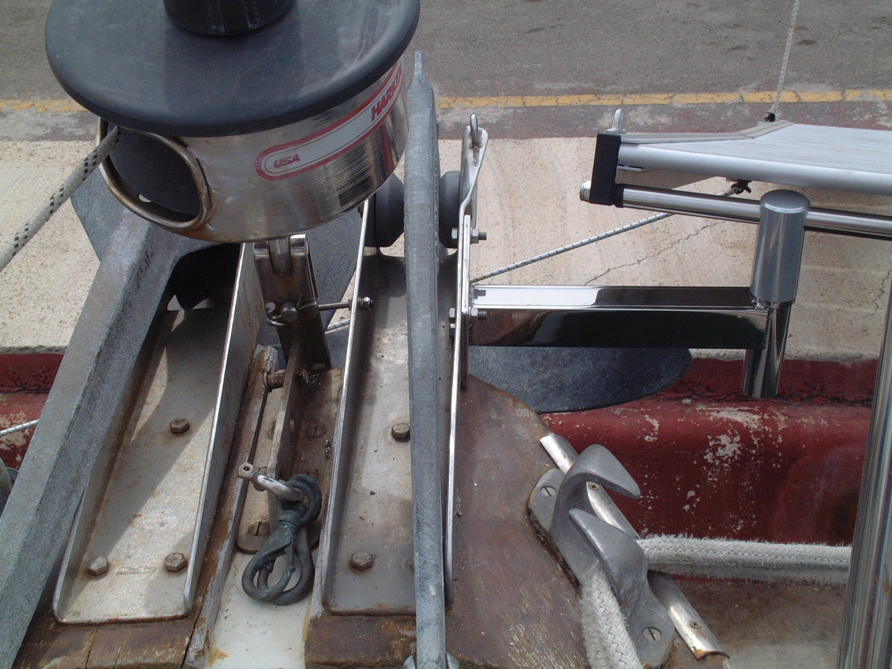 Passarelle Mount on Starboard Anchor Roller |
When I finally got to Almerimar, Spain I found just such a shop, Inox Almerimar. This is a custom stainless steel metal frabricator who offer a fairly standard Passerelle mount for bow rollers. I ordered one from Inox Almerimar and the next day they installed it. The mount is bolted to side of my starboard anchor roller as shown in the picture on the left. This mount cantilevers the socket into which the Passerelle fits outboard of the bow. As is common practice I used elastic cord as lift for the shore end of the Passerelle and more elastic cord to secure from the sides to each of the mooring bollards on the dock. |
| The normal arrangement is hold the end of the Passerelle a couple of feet off the dock as shown in the picture above. When a person's weight is brough onto the Passerelle the elastic cord stretches and that end drops onto the dock. Keeping the Passerelle off the dock will hopefully prevent small critters from getting onboard without an invitation. It doesn't not keep the feral cats that roam the dock from coming on board to check things out, but rats and other vermin would find it a difficult if not impossible jump onto the Passerelle. | |
|
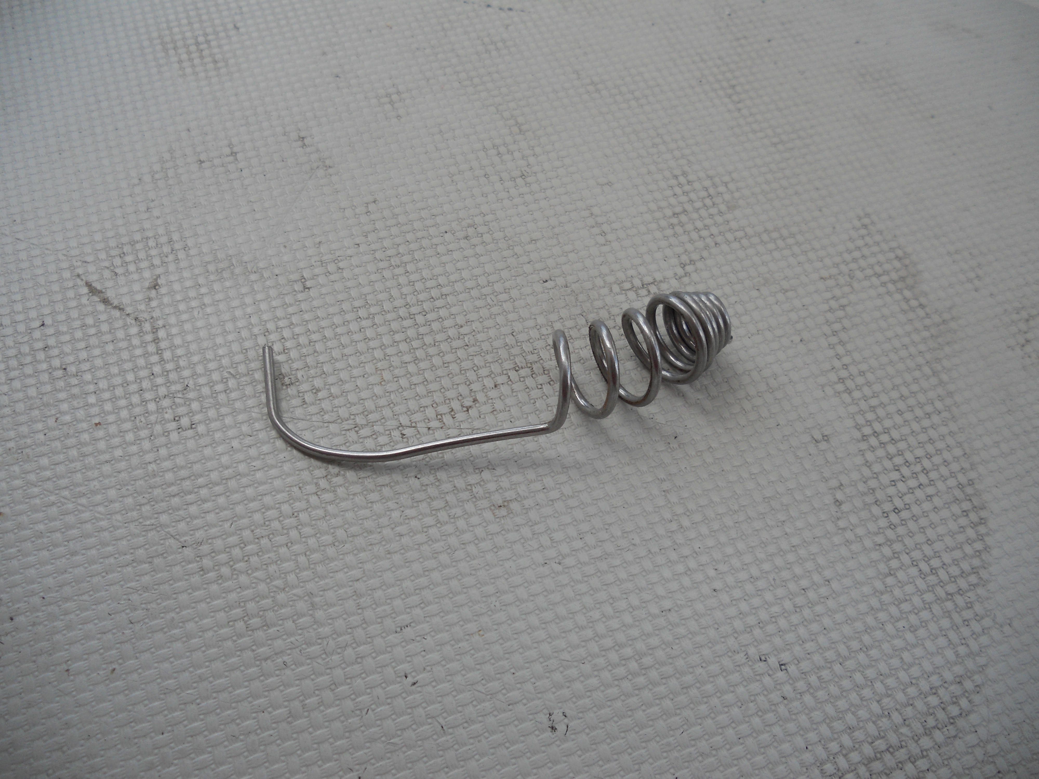
When the two ex-pat Zimbabweans (sp?), who are Inox Almerimar, initially installed the Passerelle mount it wobbled a great deal. Looking at the picture above, left you can see that the forward end of the anchor roller is secured with a single, center-line through bolt. This sufficient to counter the downward force of the anchor and anchor rode on the end of the roller, but it allows the roller to rock sideways when the force of my weight is put on the Passerelle. The solution provided by Inox Almerimar is shown in the picture on the right. They secured a hook (actually a machine screw with the head removed and bent into a hook) around the forestay chain plate to provide a counter force to the Passerelle. The mount still moves a bit, but it is now much more secure and is not flexing the anchor roller as it initially did. |
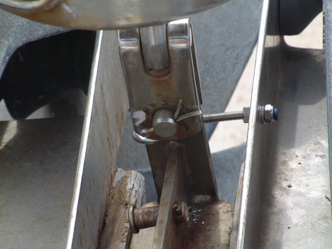 Starboard Anchor Roller Re-Inforcement |
| I sold the Passerelle to fellow American cruisers in 2007 just before my departure from Lagos, PT back to the USA. However I have kept the mount installed. It made a good foot hold when hauling up the anchor into the roller by hand. With the installation of an electric windlass in 2013 I removed the Passarelle mount and the final vestige of the Passarelle was removed from Sarah. | |
| Cockpit, 2001 | |
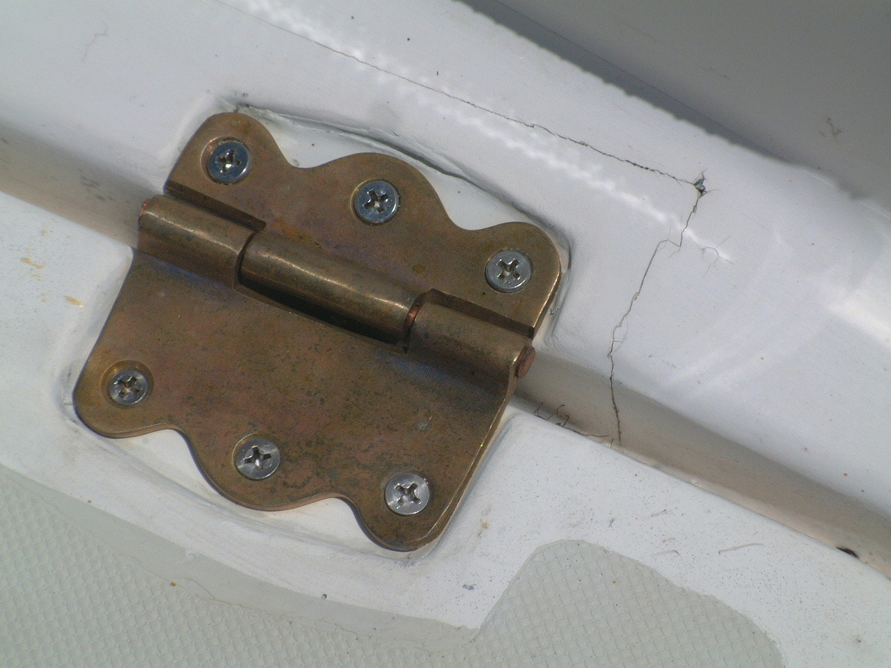 Bristol Bronze Hatch Hinge |
The hinges on all of the cockpit hatches (and the anchor rode locker) were custom made for Pearson out of cast aluminum. The pins of most of these hinges had started to fail within a year of my ownership of Sarah. Through the Pearson 424 owners mail list I got in touch with Bristol Bronze in Rhode Island who has the molds to much of the old Pearson components as well as a lot of other neat boat stuff. As their name implies they cast their products in bronze. |
|
I ordered replacements for all of my hinges in 2004.
The price was around $25.00 each, which is about the same for standard Perko
hinges of lesser quality and which don't fit the molded hinge placement on
the 424. As should be expected the holes of the new hinges did not align perfectly with the holes from the previous hinges. So I did have to fill the old holes with fiberglass putty and drill new holes. Bristol Bronze is a company I can fully recommend as one that produces quality products and meets their commitments. The two times I tried to use the email address on that web page returned errors. You'll probably have to call, in which case it may be difficult to get off the phone because the owner does like to talk. |
|
| The fine line in the fiberglass around the hinge in the close up picture is how the previous owner was able to fit the Northern Lights Generator into the lazarette locker. He had about 2" of the aft edge of the locker cut out to make room for the installation, and then re-glassed with the installation was complete. Obviously if I need to remove the generator it will either come out in pieces or I will have to repeat that procedure. |
 Aft Cockpit Lazarette |
| The access ports shown above the lazarette hatch were installed in 2004, primarily to facilitate the removal of the old davits, which were sold on eBay, and to facilitate the installation of the Monitor Wind Vane (see, above) | |
| Cockpit Lighting, 2009 | |
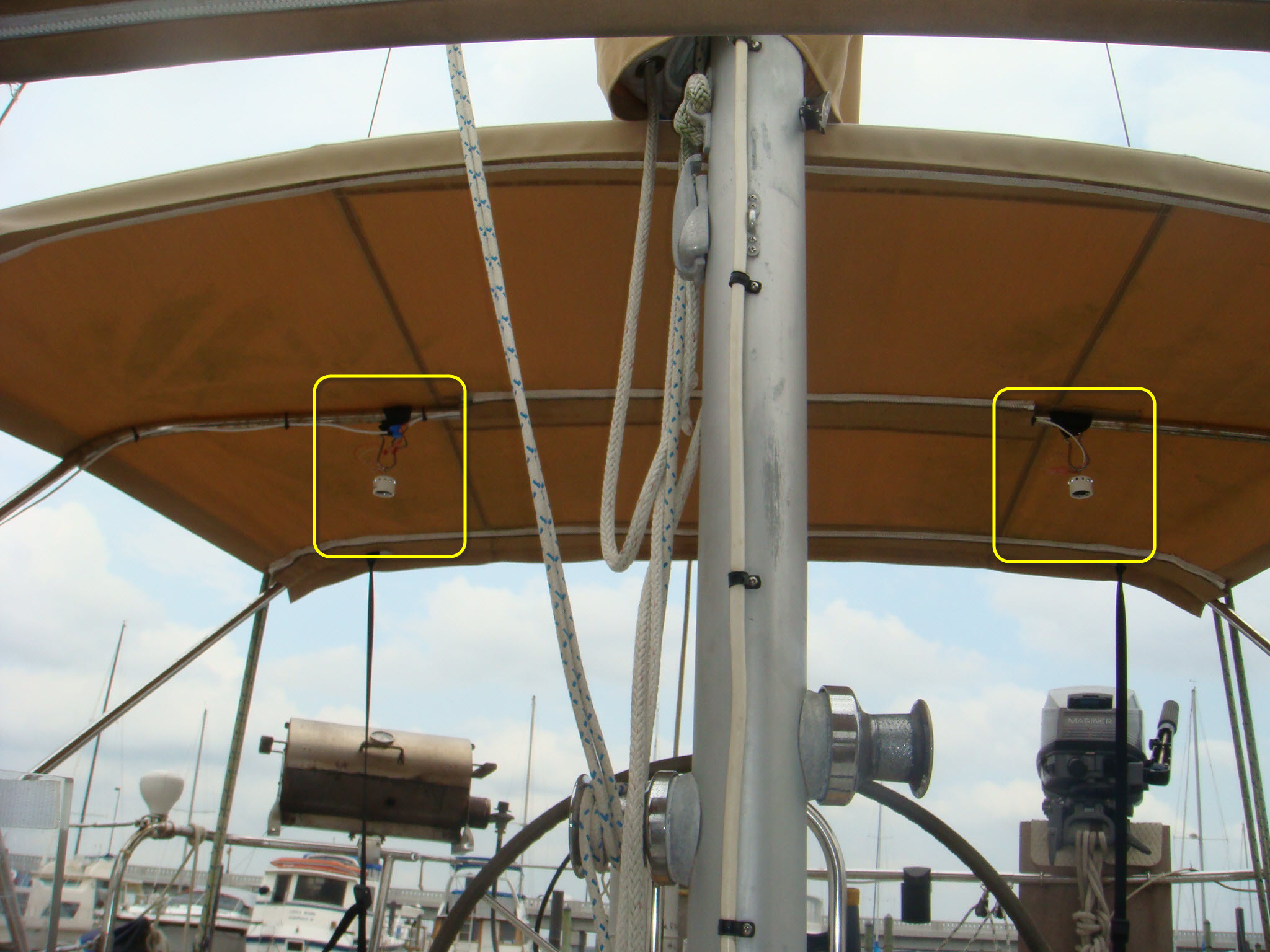
LED Cockpit Lights Under the Bimini |
At the time I bought Sarah the previous owner had installed a spot light on the mizzen mast which provided light for the cockpit. This worked reasonably well except it used a lot of watts and did not provide much illumination for the cockpit aft of the mast. When I installed the Bimini there was no illumination aft of the mast. Finally the bulb in the spot light burned out. |
| Rather than replace the bulb I decided to install two LED lights from Bebi Electronics under the Bimini (highlighted by the yellow boxes in the picture above). These lights should provide ample lighting under the Bimini to make dining in the cockpit possible after dark. | |
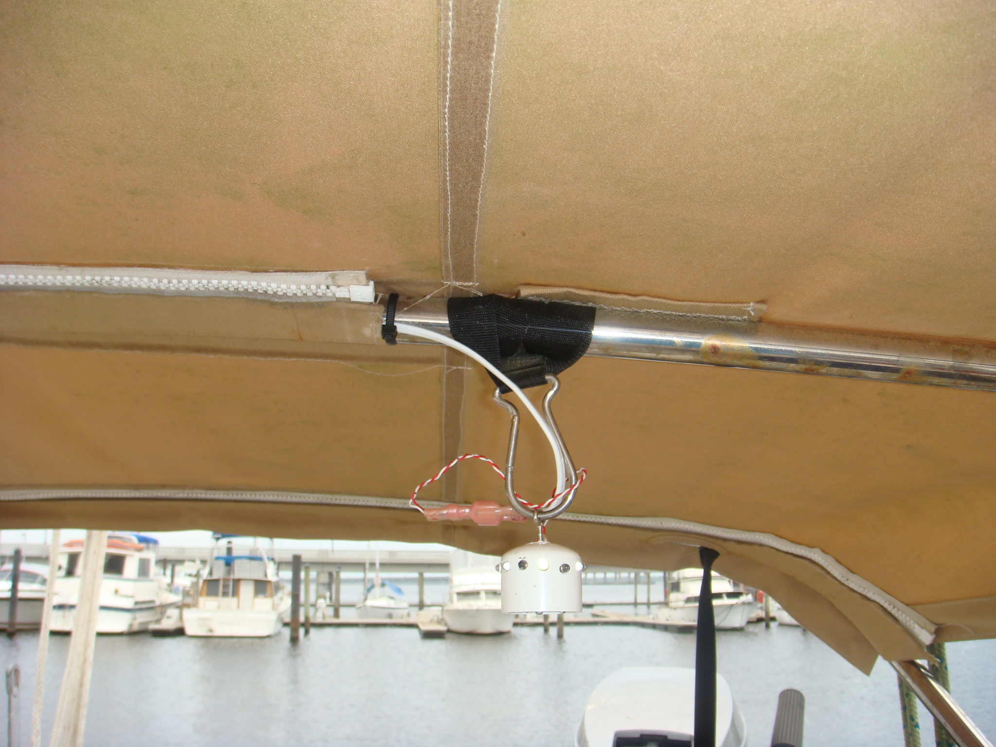 Mounting Clip Has Seen Been Replaced |
Initially the lights were hung by clips on the middle frame of the Bimini. One or
both of the lights can be removed by disconnected the blade type wire
terminals then unclip the light from the Bimini frame. I subsequently replaced those clips with cable ties. The lights aren't so easily removed, I don't hit them with my head quite so often. |
|
Now
I can cook, dine and just hang-out in the cockpit after dark. These LEDs will also provide an alternate or additional anchor light. |
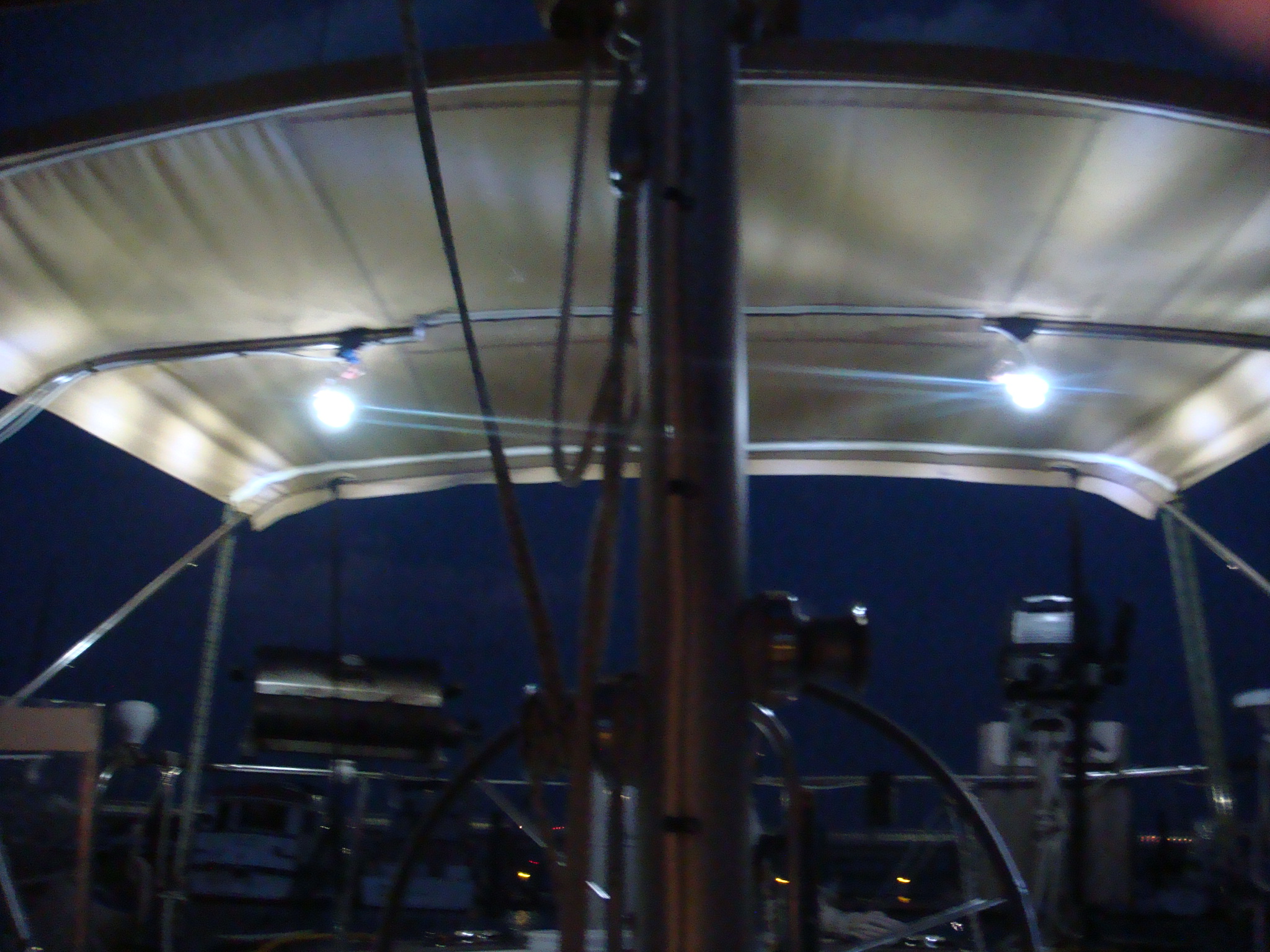 Cockpit Illuminated After Dark |
| Solent Stay (see also pages on The Solent Stay and Finishing the Solent Stay), 2004-2009 | |
| A
Solent Stay is an inner-forestay that is attached close enough to the
headstay fitting on the masthead (normally near the Black Band) such that
running backstays are not required to keep the mast in column. Solent Stays
are also normally removable as they are so close to the forestay that even a
Yankee, much less a Genoa, will not easily tack between the two stays. The
Solent Stay is very useful for off-shore sailing, but can be a hindrance for
in-shore or coastal sailing. Hence it can be removed and secured out of the
way to allow easier tacking of the Genoa. The purpose of the Solent Stay is to set a staysail for off-shore sailing. The smaller area staysail, with its tack located well inboard from the stem of the boat is a much more easily controlled and managed sail when the wind is above Force 5 or 6. In those winds a Genoa must be partially furled, which still puts a lot of sail area at the end of the boat and puts a lot of stress on what is really a light air sail. | |
|
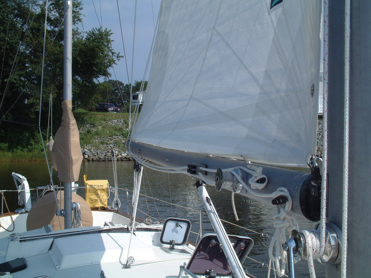
In preparation for the start of Sarah's Atlantic Circle, I had a Solent Stay rigged on Sarah by Mack Sails & Rigging of Stuart, FL. Details of the Solent Stay and the sources I used to come up with Sarah's rig are documented on the Solent Stay page. It is a little difficult to see in the picture on the right, but this shows the newly installed Solent Stay. If you double click on the picture it will open the full resolution picture in a separate window. |
 Sarah's Solent Stay |
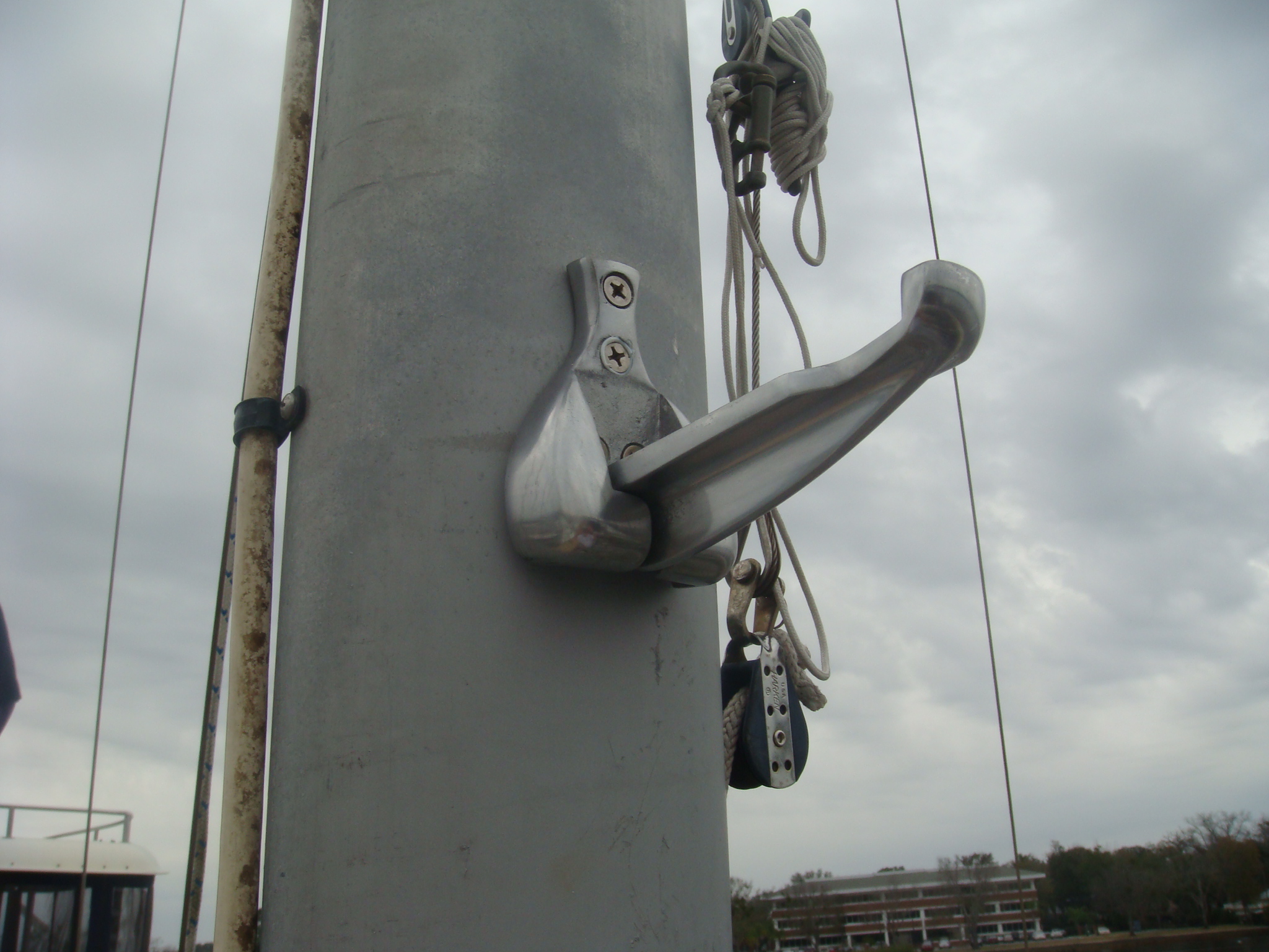
 Highfield Lever |
On the left is a picture of the Highfield Lever that is used to release and remove the Solent Stay. |
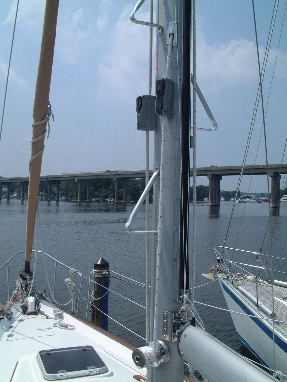
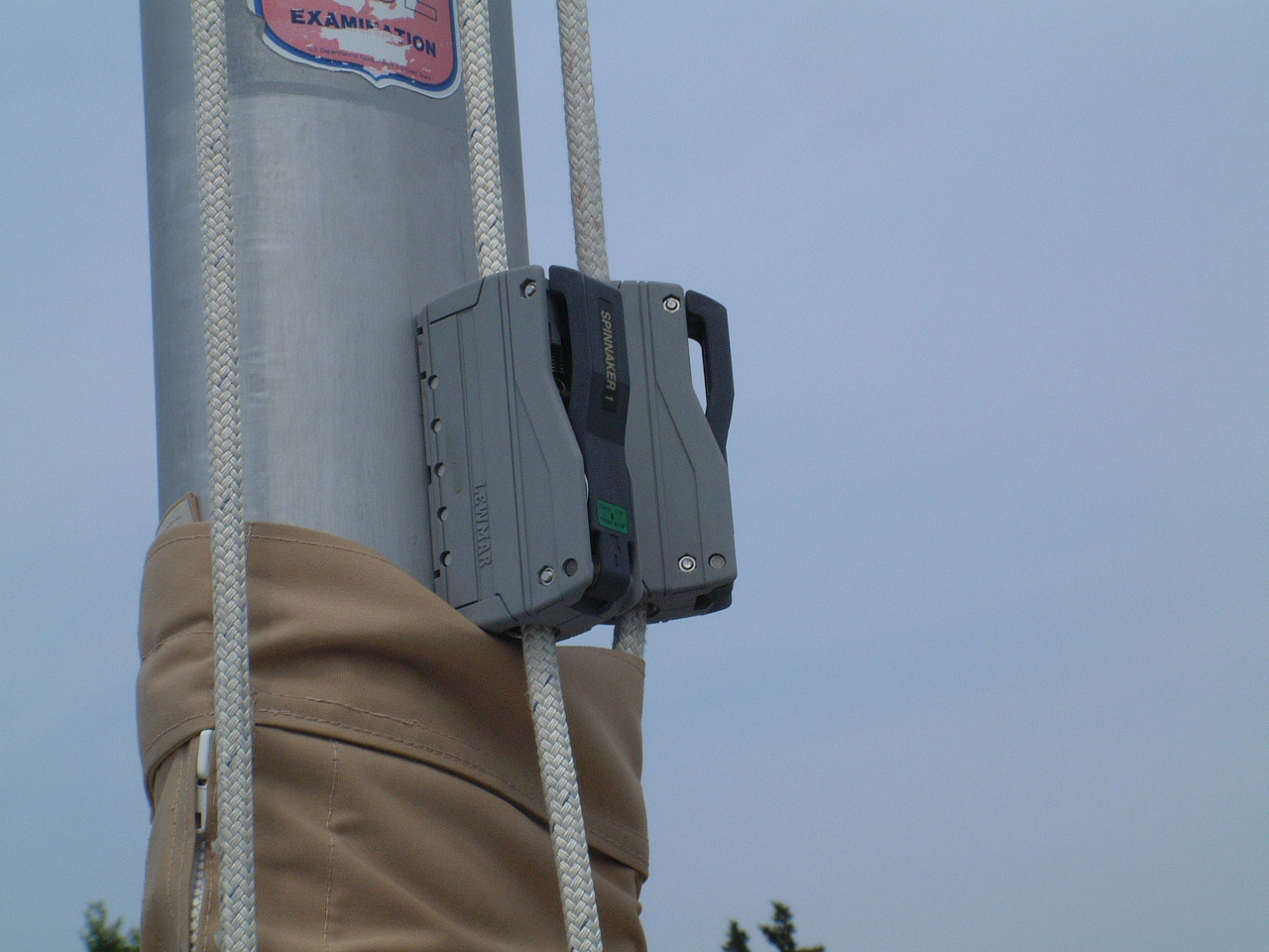
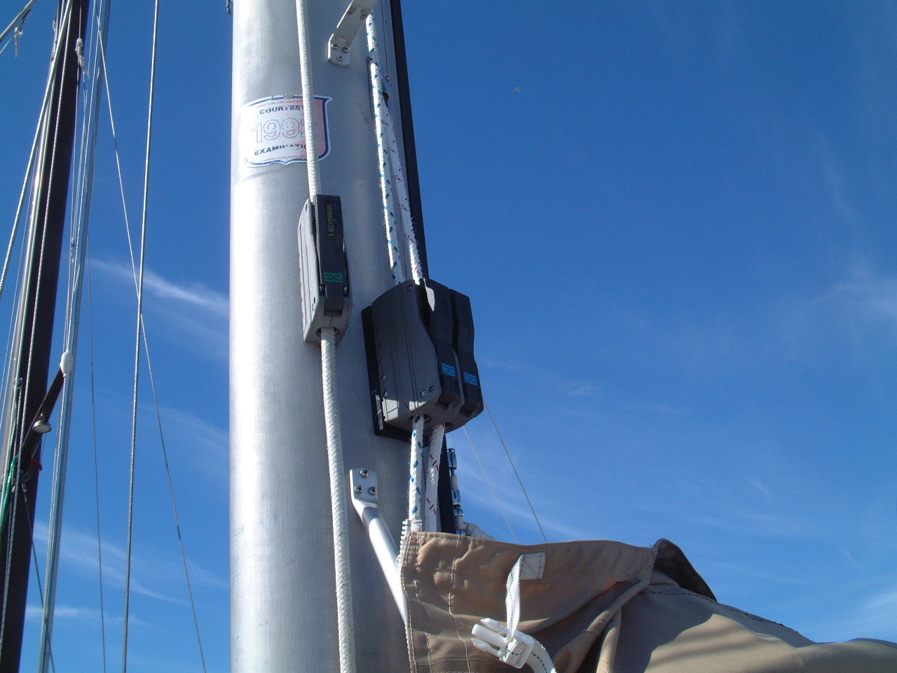
| After the Solent Stay was installed and a new staysail bent on, I discovered the halyard did not provide a fair lead to the Genoa winch on the mast. The halyard goes through a swivel block on the Wichard fitting on the front of the mast. The lead from that block to the winch puts the halyard against the port spreader. This would produce a lot of chafe on an extended sail. Before we left Fort Pierce for Portugal I didn't have a chance to work out a solution for this problem. Fortunately we had fair weather all the way across the Atlantic, and the staysail was never needed on the crossing. | |
|
When I finally berthed Sarah in Cascais, Portugal Jack & Patricia Tyler were berthed on Whoosh at the Doca de Alcantarra in Lisbon. Since I stole most of the Solent Stay design from Jack, when I visited them I checked out how they took care of the halyard lead problem. The solution was simple - a cheek block on the forward lower part of the mast to lead the halyard down the front of the mast, away from the spreader, and turns the halyard to the winch. My implementation of this design on Sarah is shown on the right. I added a Spinlock rope clutch to free the single halyard cleat on that side of the mast. |
 Rope Clutch and Cheek Block for Staysail Halyard |
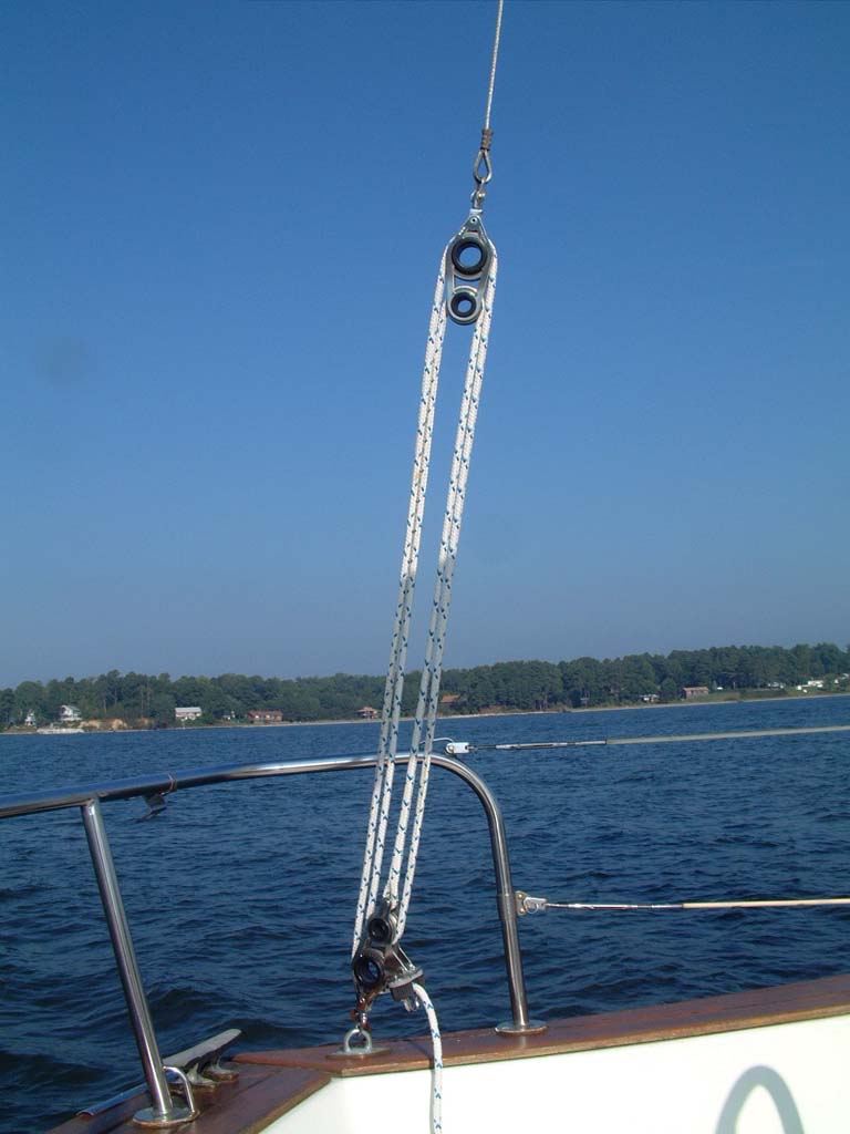
| Preventer, 2011 | |
|
For the first 11 years I've owned Sarah, my preventer for the main sail boom
was the tackle on the rigid boom vang. I would remove the tackle from
the vang and attach it between the forward boom bale and the stanchion base
abeam the mast. It worked, or at least it didn't fail me for two ocean
crossings and a lot of sailing off the East Coast of the USA. Though
it worked I was never comfortable with the arrangement. It did not
provide a sufficient forward lead to absorb a violent jibe. On a controled
jibe there were several minutes on the new tack where there was no preventer
while I moved the tackle from one side to the other. Handling the
tackle sometimes meant leaning out over the lifelines on a rolling boat.
I knew the solution - a preventer line that ran from the end of the boom to
a block near the bow and then back to a cleat or rope clutch in the cockpit.
However, I never could come up with a design that didn't present equal or
greater problems than my existing arrangement. Then I attended an SSCA Webinar hosted by Beth Leonard where she described the preventer arrangement on Hawk. This looked like a workable solution for Sarah. |
|
| To be effective the preventer should be easily set up without requiring someone to go to the bow of the boat. The solution on hawk was to have both preventers run on deck at all times. To keep this from cluttering the deck with lines and entangling other lines they separated the preventer lines into two pieces each. The shorter pieces are attached to the end of the boom and run down the boom to near the gooseneck where they are clipped to the boom when not in use. The other pieces run from the cockpit down each side of the boat, outboard of the lifeline stanchions to swivel blocks near the bow, then back down the outside of the lifelines and all rigging to a stanchion near and aft of the mast. This end of the line is terminated with a shackle that can be clipped into an eye on the end of the line on the boom. When not in use all of the preventer lines are out of the way of the other running rigging and do not interfer with moving on the side decks. To engage the preventers, one person need go on deck only as far as the mast to unclip the deck preventer line from the stanchion and attach it to preventer line on the boom. Now the preventer can be tensioned from the cockpit. When jibing both preventers can be rigged allowing a crew member in the cockpit to control boom movement. | |
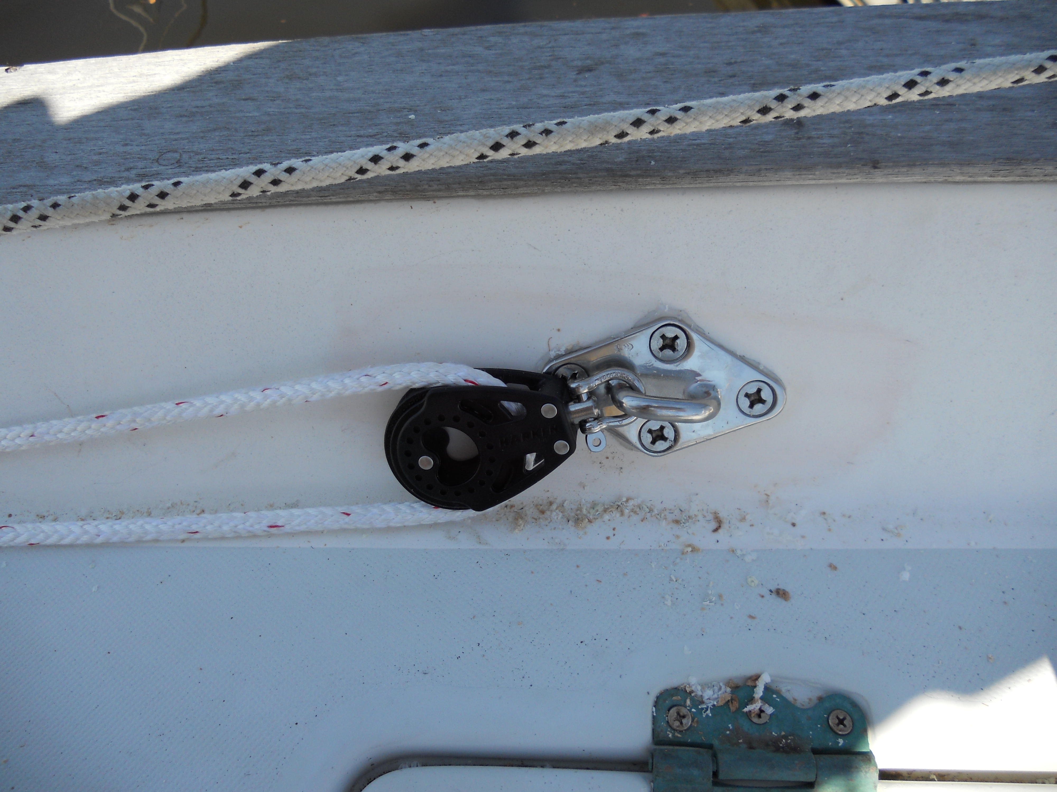 Padeye and Block on Port Rail |
Well, it looks like a great solution, now all I had to do was rig one on
Sarah. I decided to rig one side first so I didn't double my screw-ups. First I thru-bolted (with large fender washers) a padeye to the portside rail about 1' aft of the Mast Pulpit stanchion. I used a larger than required padeye because I will use this padeye to secure the forward end of the jackline as well. |
|
The block should articulate sufficiently to provide a fair lead to the boom
without the line rubbing on the cap rail. If I've miss-judged (have I
ever?) that lead I will extend the block with a D-shackle. Then I ran 3/8" line through the block and down the deck to the cockpit. I still have to find a suitable site for a rope clutch or cleat to secure the end of the preventer. |
 Preventer Line in the Block |
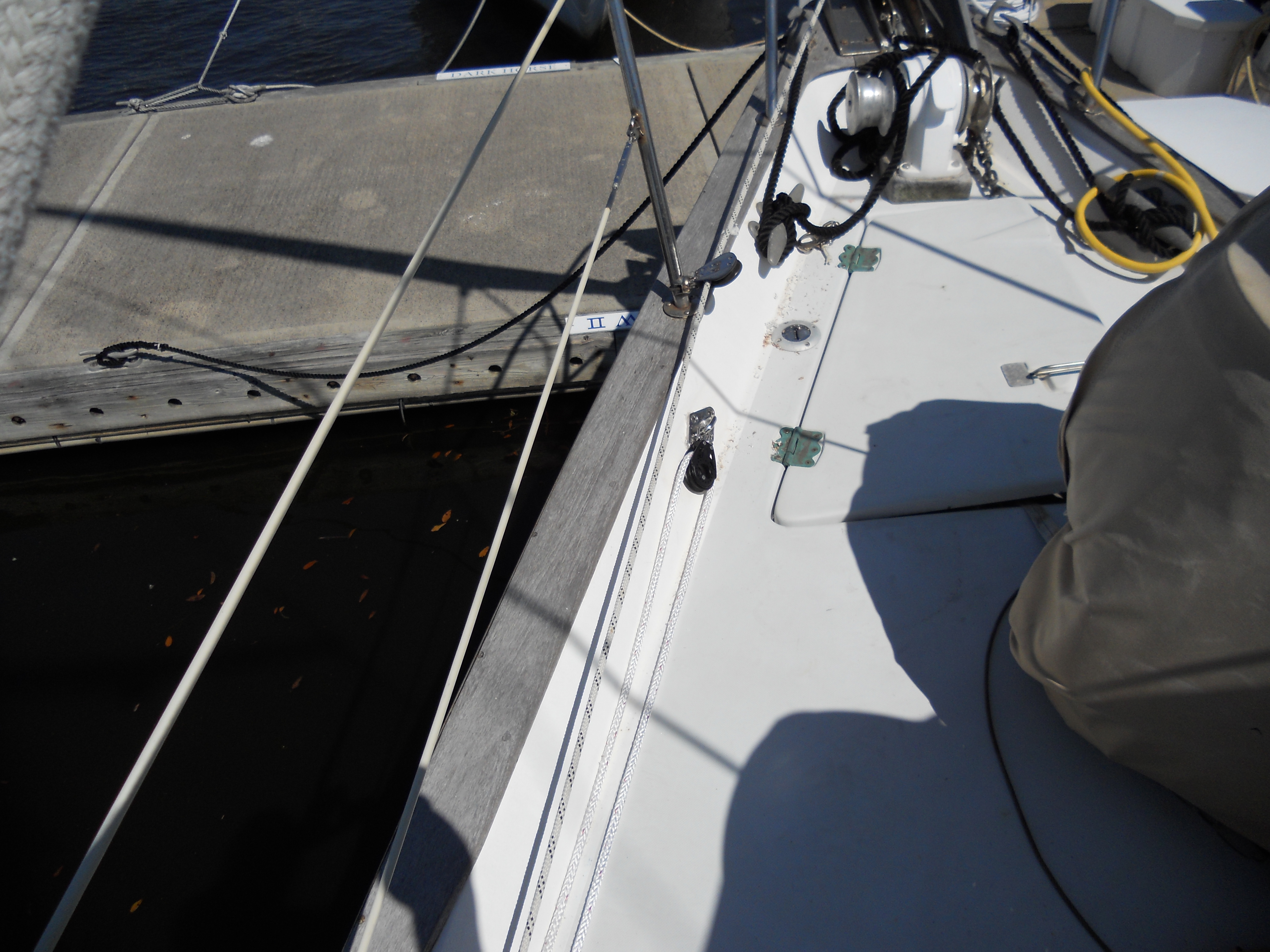
 Gahauer and Schaefer Stanchion Blocks |
I
used two Garhauer stanchion blocks to guide the line outside of the first
and last lifeline stanchions. On the port side the Preventer line runs above the Genoa
furling line. These blocks are not as elegant as the Shaefer blocks (below the Garhauer) I use for the furling line, but they appear very effective and cost about 1/2 the cost of the Shaefer blocks. |
| For the intermediate stanchions I used a Spinlock stanchion fairlead. |
 Spinlock Stanchion Fairlead |
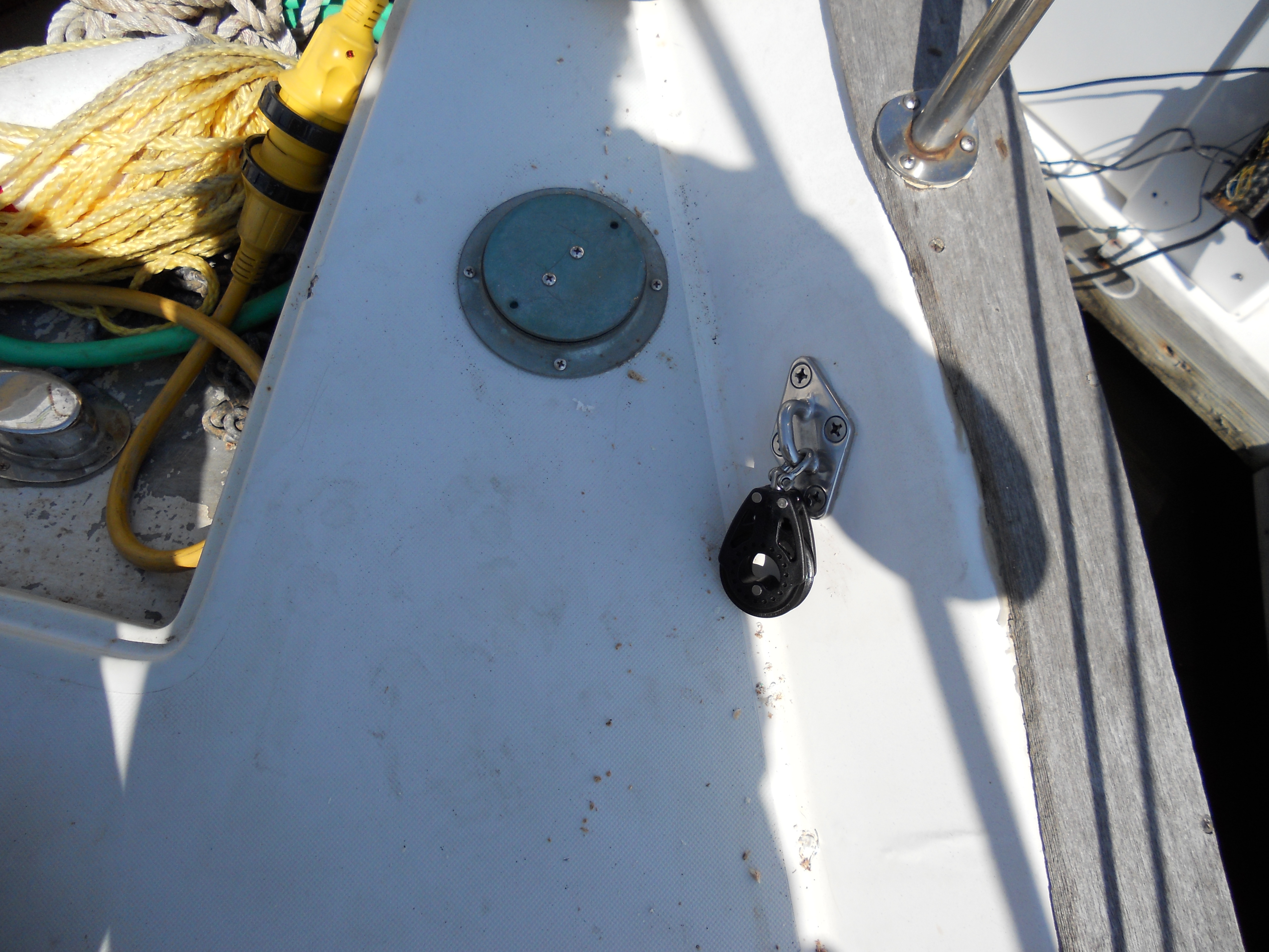 Starboard Preventer Block |
Installing the padeye on the starboard side was little more difficult as
there is more deck to reach under. This was just about the limit of my
reach. I also found out the bases on these padeyes are not symmetrical. I drilled the holes with the machine screws inserted to hold the base in position. Then I removed the screws and base to bed the fitting. I attached two of the ma;chine screws and discovered that the remaining holes were not alighned with base. I had to drill out those holes. |
| Apparently I flipped the padeye around from when I drilled the holes. I must have just lucked out on the port side and attached the padeye in the same orientation as when I drilled the holes. | |
| I attached a padeye on each side of the end of the boom, just below the reef line hardware. The short Peventer line will be terminated at this padeye. The one thing that concerns me about these padeyes is that they are held in place with machine screws threaded into the boom wall. This provides a lot of shear strength for the attachment, but much less strength for a load perpendicular to the base (I used 1/4"-20 screws). I estimate the load on the preventer line will be about 60º from the base. The shock load from a violent jibe might pull the machine screws loose. |
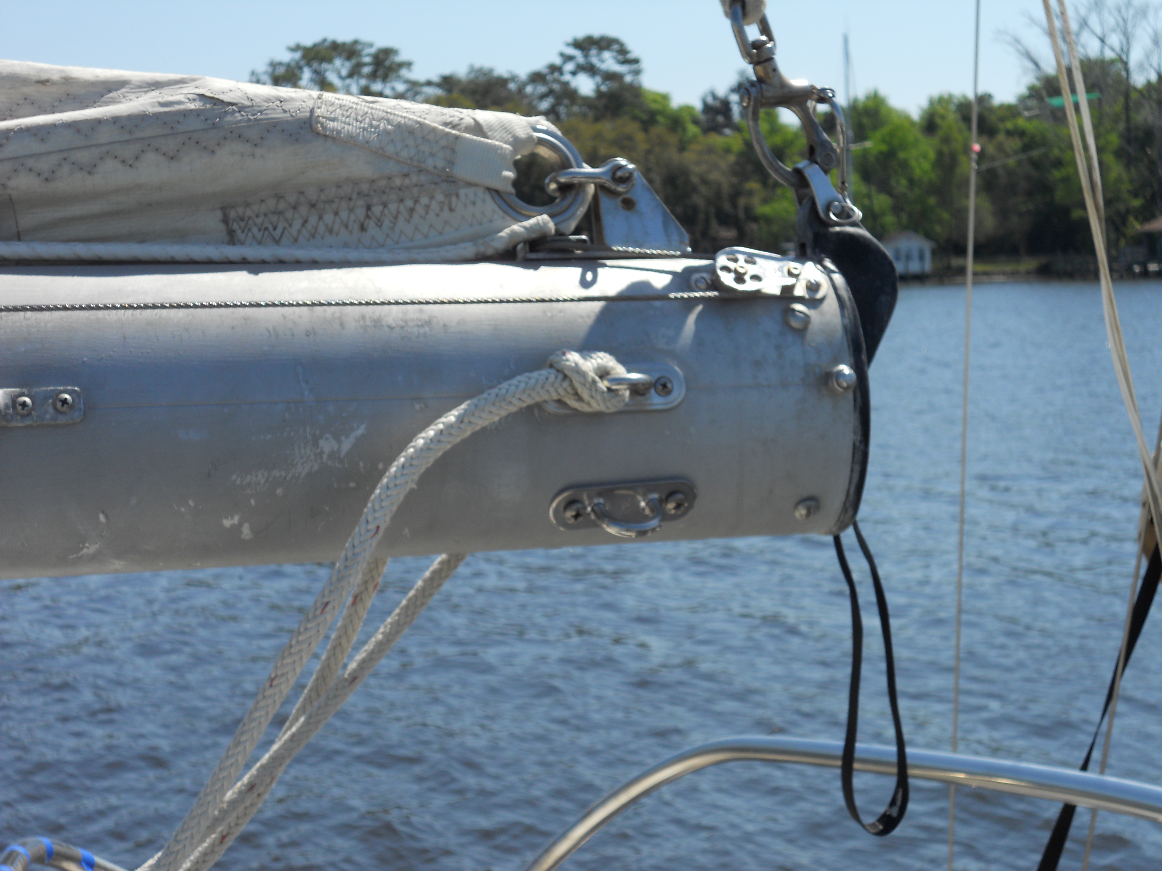 Padeye on End of Boom |
|
I'll have to think about this arrangement a bit. A couple
of my options:
At least now all of the hardware is in place except for the cockpit cleats/rope clutches. |
|
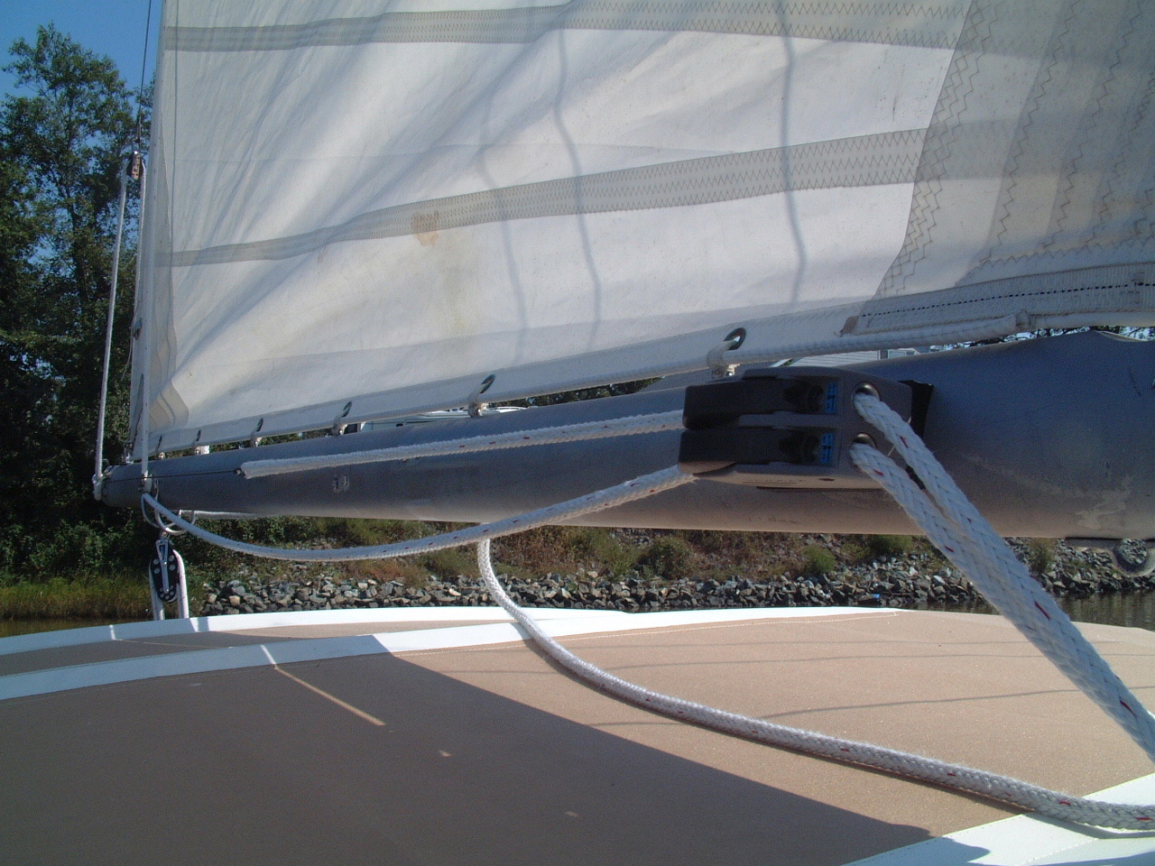
 Preventer Line Rigged on Boom |
Today,
March 19, I completed rigging most of the preventer lines. On
the left is the starboard boom line attached to the padeye below the turning
block for the reef line. I spliced an eye in that end of the line
large enough to pass the thimble at the other end. This allowed me to
attach the line to the padeye without a knot, but it is still removable
without having to cut the eye. The two padeyes at the end of boom were not installed symmetrically. I needed to install the starboard padeye lower than the one on the port side to avoid interference with the reef line cheek block. |
|
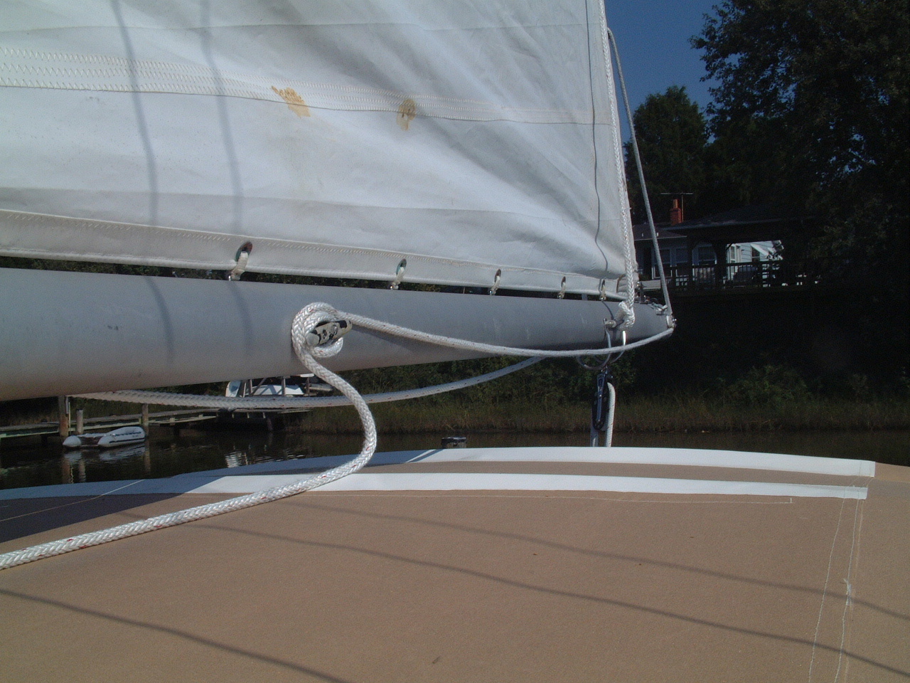
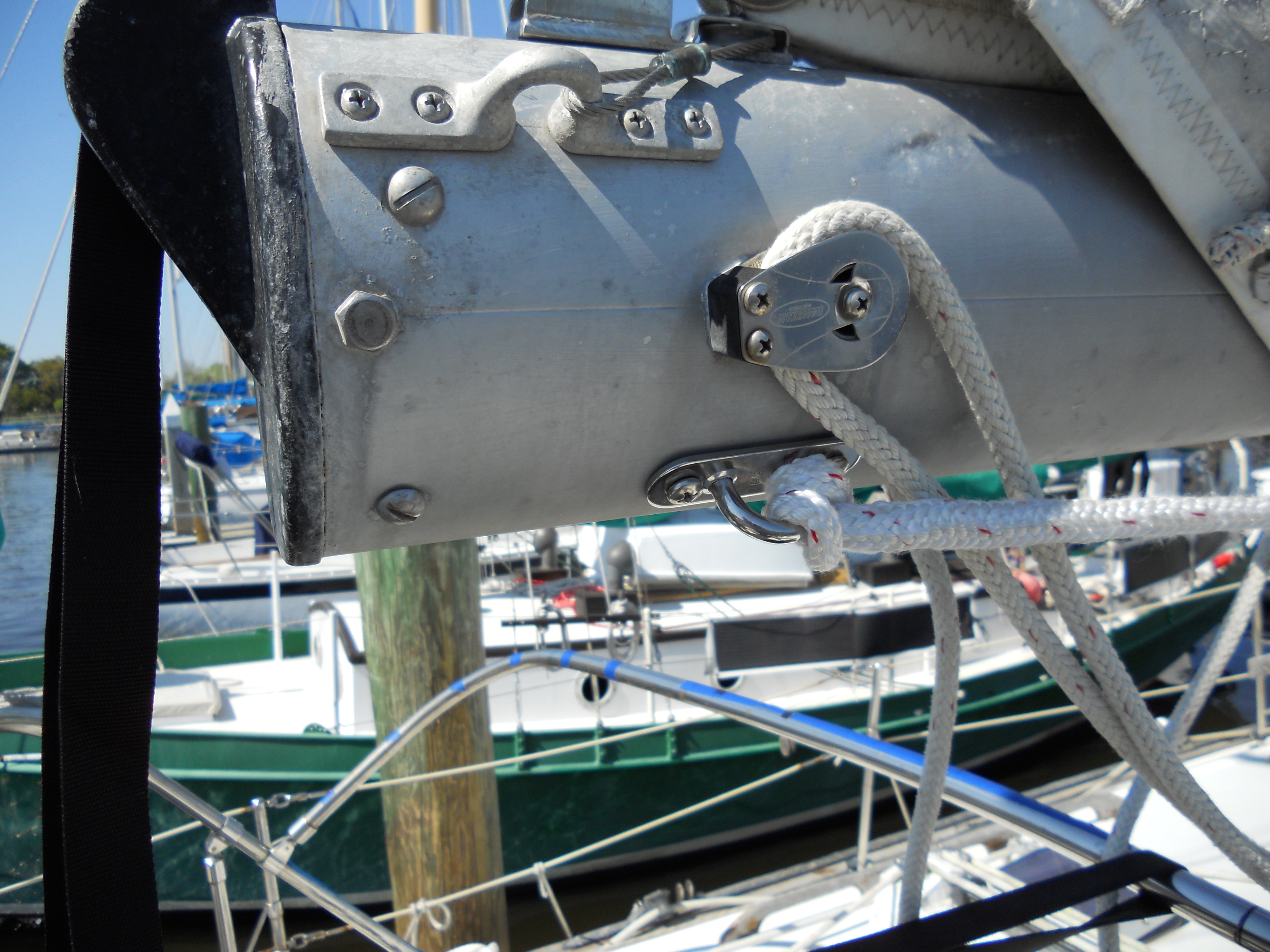
On
the right is the other end of the boom line. I spliced a SS thimble
into this end as it will have to take the wear of the shackle on the end of
the deck line. For now I'm using 3/16" shock cord to secure the line to the boom. This doesn't look like a good solution as the line will interfere with handling the reef lines. I may need to shorten the preventer line and/or route it along the bottom of the boom. |
 Elastic Cord and Hook to Secure Boom Line |
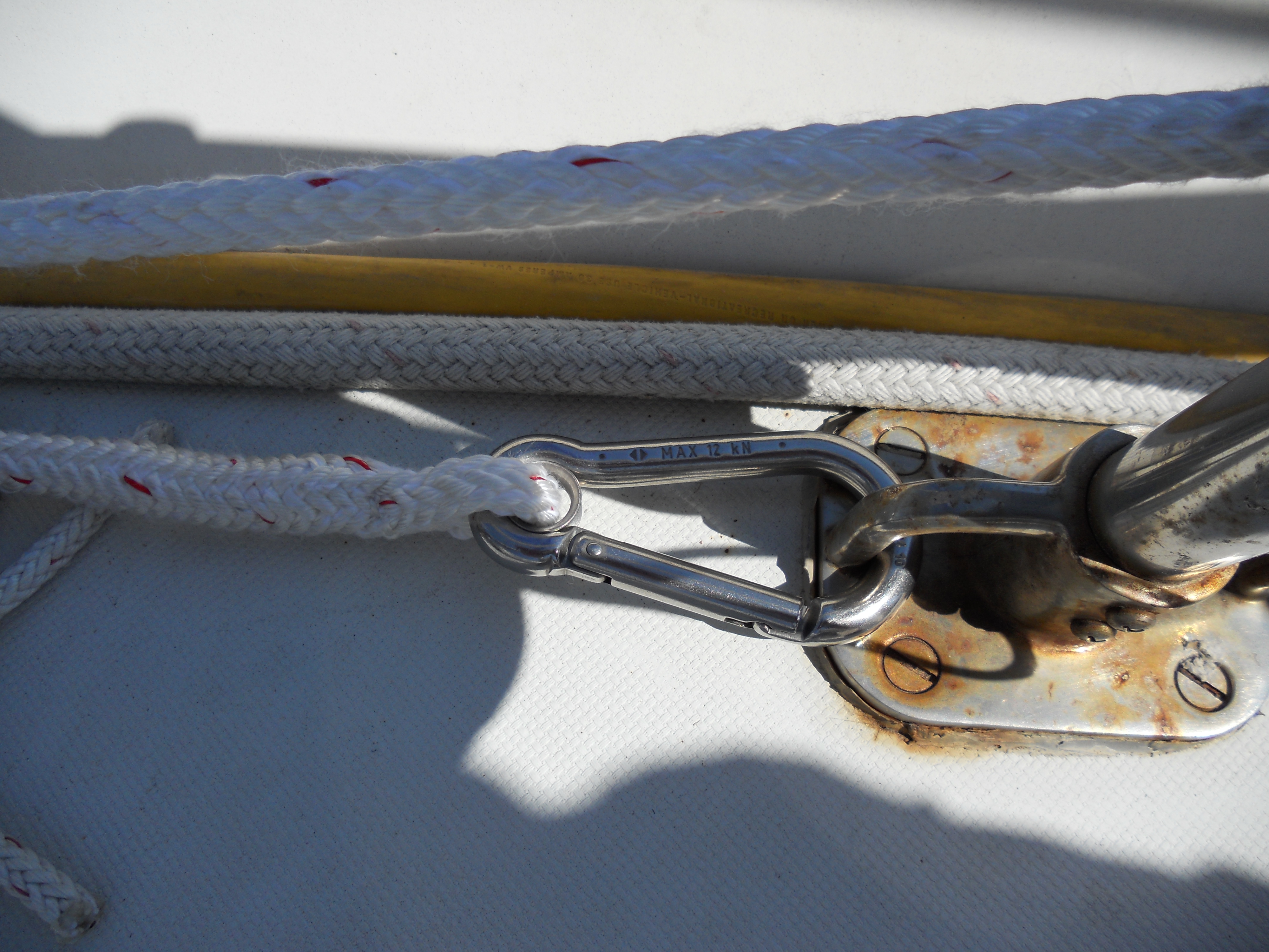 Carabiner Clip on the Deck Line |
I spliced a Carabiner shackle to the end of the deck line. I don't trust
snatch shackles that much and Carabiners are easy to connect and disconnect. That was a total of 5 eye splices today. By the 5th one I was actually getting pretty good at it. I still have one more splice to make on this project. I did not have enough line for the port deck line. I need 60' for each deck line and I had only 20' left when I finished the other three lines. |
| That hook and elastic cord solution for stowing the on-boom portion of the preventer lines lasted one demonstration of how the two pieces are hooked together. That wire hook bent into a useless mess. So in addition to the starboard perventer interferring with the reef lines, I also had to come up with a better way to stow these lines. |
 Wire Hook Did Not Work |
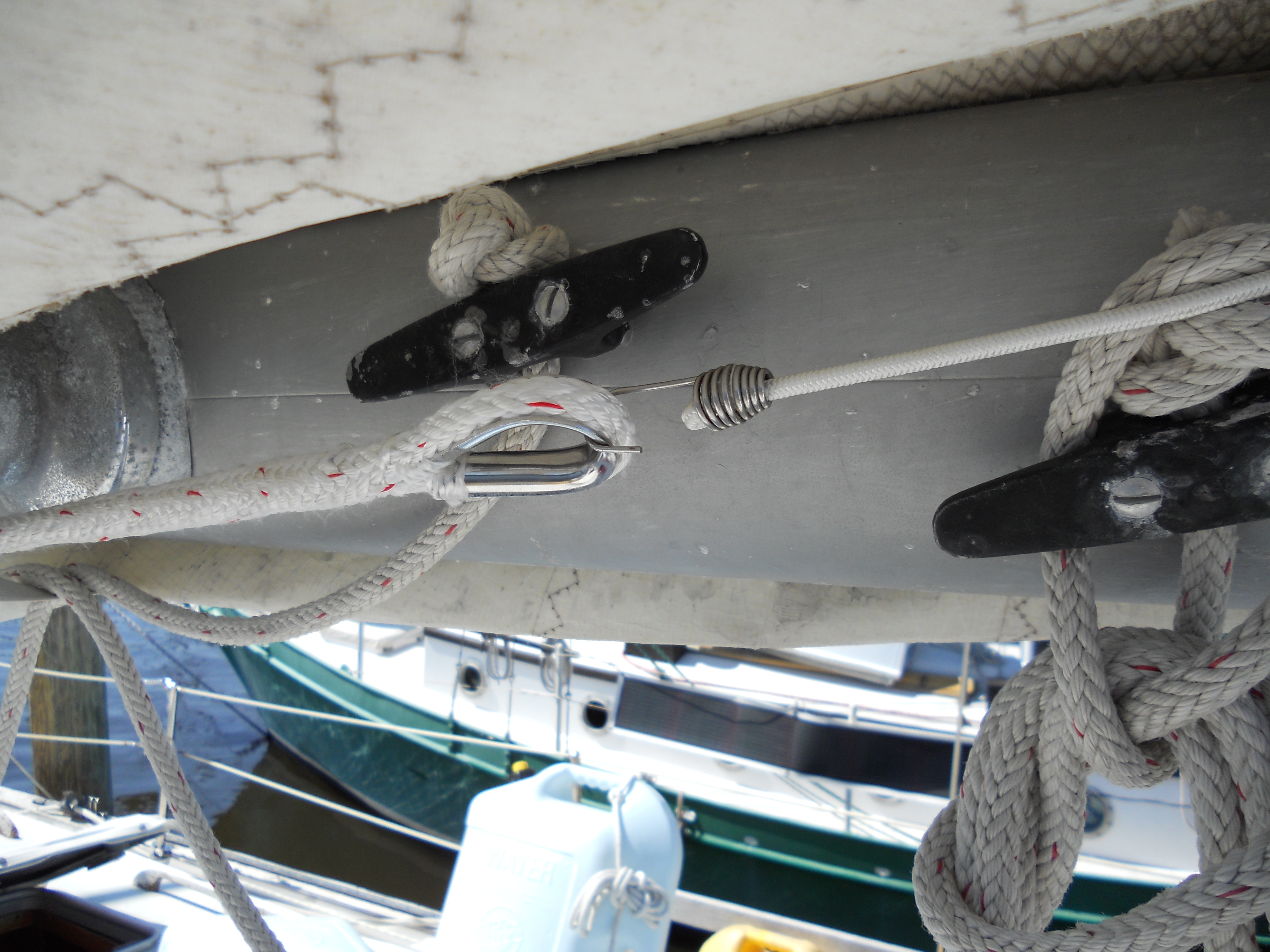
 Eye Strap and Shackle to Secure Boom Lines |
On
the left is a picture of my solution to the problem. I screwed a
couple of eye straps into the bottom portion of the boom. My original
intent was to once more use elastic cord to tension the preventers, this
time using somewhat more substantial shackles. |
| However I discovered that I placed the eye straps a little too far aft of the end of the boom and there was not enough room to rig elastic cord. I did luck out and I could place the shackles in the eyestraps, and with a little tug on the preventer lines, secure them in the shackles. This is much more secure than using elastic cord. This arrangement also leads the preventer lines along the bottom of the boom, out of the way of the reef lines. | |
|
When I stopped work on the preventer rig in 2011 there was still one more
task to complete - install some way to cleat the preventer lines. My
thinking was to use a rope clutch instead of a standard cleat. I've
installed a number of rope clutches on Sarah, mostly for halyards. I
like the ease of operation of the rope clutches, especially the ability to
tighten a line without releasing it. In April, 2011 time was running short for a haulout and the trip back North. So for the interim I just secured the preventer lines to the stern mooring cleats. |
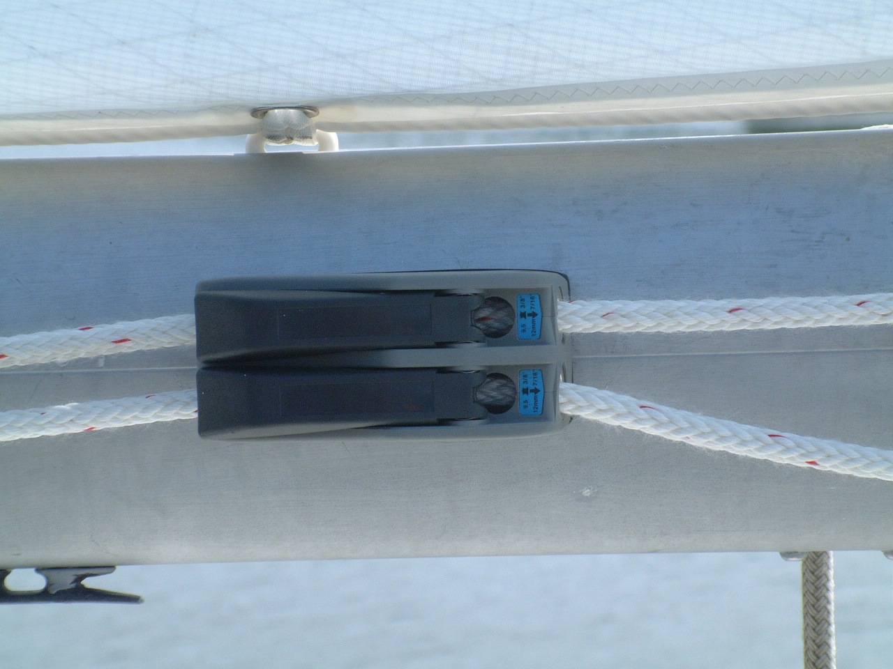
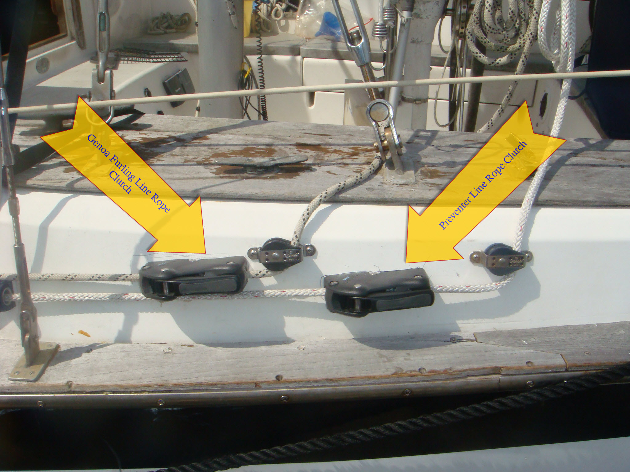
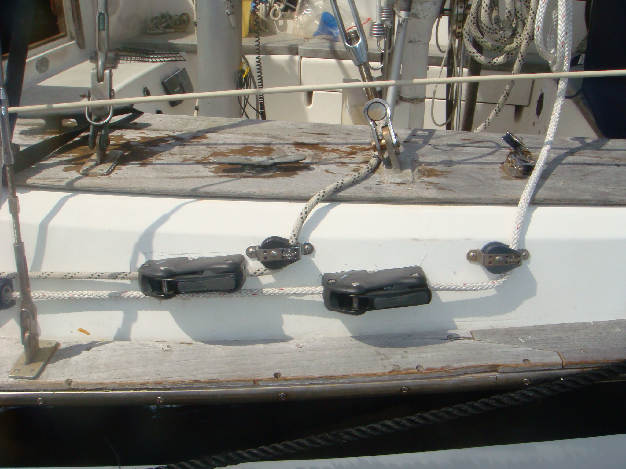 Rope Clutches and Cheek Blocks for Port Preventer and Genoa Furling Line |
 Rope Clutch for Starboard Preventer |
In March, 2012 (back in Jacksonville) I completed the preventer project by installing the rope clutches on the outside of the cockpit coaming, as shown above, below and on the left. |
|
The rope clutch for the Port preventer is the one further aft. I used the
cheek block from an earlier failed attempt to put a rope clutch on the Genoa furling
line. At same time I installed a second rope clutch and cheek block
for the furling line. Although I've used Lewmar rope clutches exclusively in the past, for this application I used Spinlock clutches. |
 Looking Forward on the Port Side |
 Looking Aft on the Port Side |
The there are two advantage of this rig:
|
| Genoa Furling Line Control, 2001-2012 | |
| When I purchased her, Sarah was equipped with a
Harken furling system for the Genoa. Although I've had some halyard wrap
problems with this set up, it performed satisfactorily for the first five
years I've owned Sarah and is still in use. The one part of the furling
system on Sarah that did not work well was the furling line.
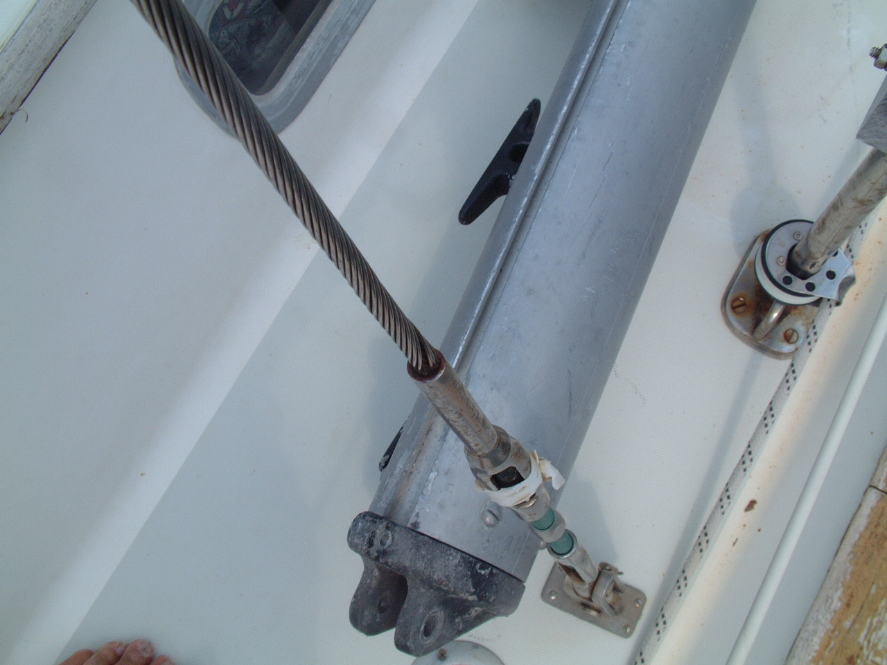
When I took possession of the boat the furling line was lead through two small blocks attached to two of the port stanchion bases back to a small cleat on the cockpit coaming. The fixed shackles that attached the blocks to the stanchion bases did not allow the blocks to articulate into a fair lead for the line. The line lead from the drum caused it to rub on the drum housing and the blocks themselves did not align well and did not provide for a low friction lead back to the cockpit. Further the lead into the cockpit, when the line was under load, caused it to rub against the lower mizzen shroud turnbuckle. Initially I tried to address the problem of leading the line out of the drum and down the deck. I replaced the two blocks with purpose-built blocks that attached to the stanchions and provided a fair lead. The problem with these blocks is that they lead inside of the stanchions and were a great ankle-banger when working that side of the deck. To fix the drum lead problem I added a Harken ratchet block at the base of the aft stanchion on the bow pulpit. This provided a fair lead out of the drum and to the first of the stanchion blocks described above. This change greatly improved the operation of the furling line and removed all of the chafe and friction issues that I inherited. However, the operation of the furling line was still awkward in the cockpit as the mizzen shroud turnbuckle was still in the way. This was a livable situation while I was sailing Sarah on the Chesapeake on weekends. When Mike Repass and I took her off-shore for the start of the Atlantic Circle, the limitations of the system were apparent and bothersome. |
|
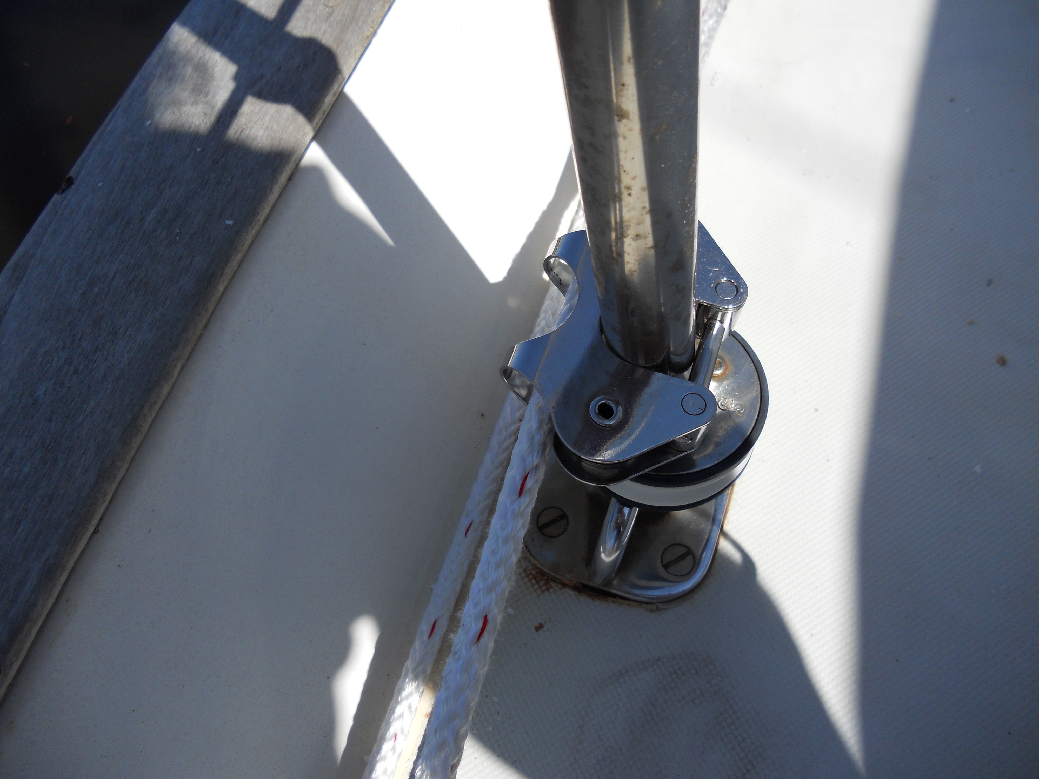
| We lived with the issues for that voyage, but I decided to find a better solution before I resumed sailing Sarah in Europe in 2006. The first thing I did was to replace the stanchion blocks with a new design from Schaefer that puts the sheave completely around the stanchion (see picture on right) and leads the line outboard of the stanchions. This was not a major improvement, but it did address the ankle-banger problem. |
 Schaefer Stanchion Block |
|
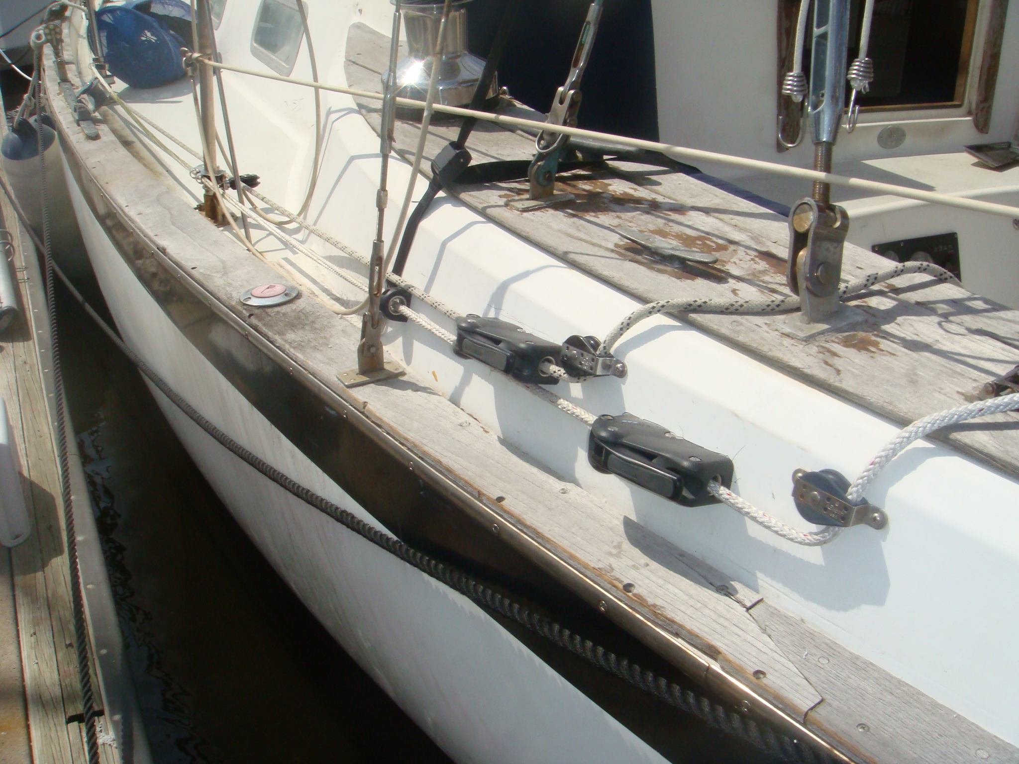
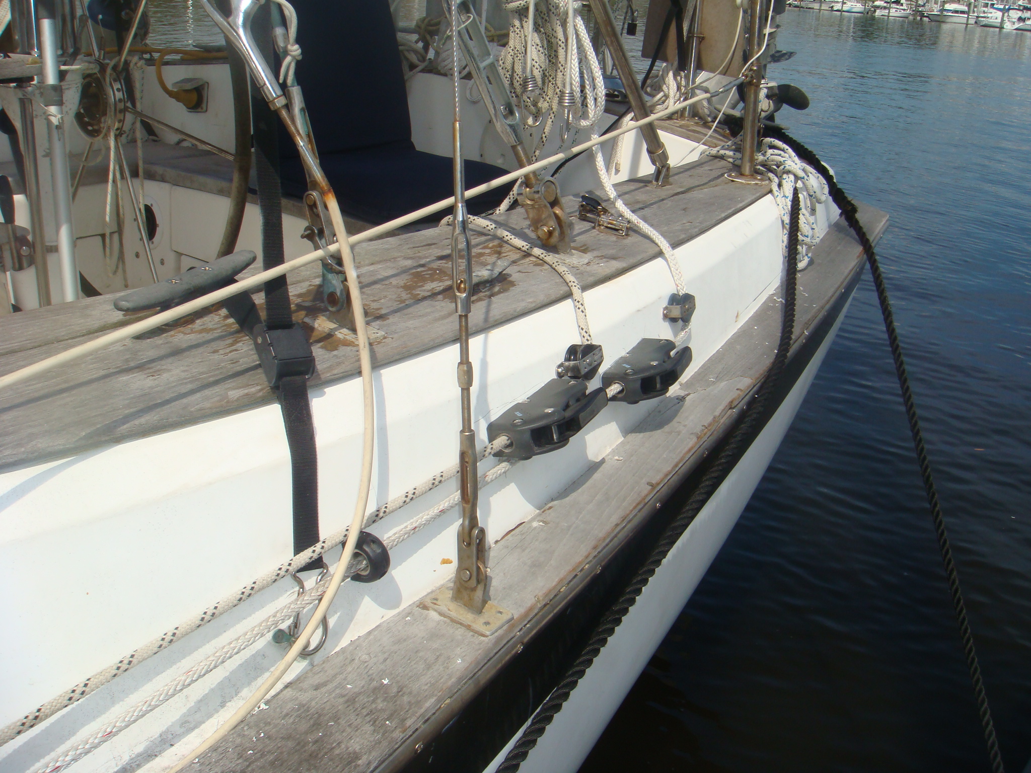
The second change was to route the furling line down the outside of the cockpit coaming, through a small Spinlock rope clutch, then to a cheek block and back to the cockpit. This arrangement is shown in the pictures on the right. Now the lead into the cockpit avoids the mizzen shroud completely and provides better leverage on the line. The rope clutch eliminates the need to hold pressure on the line while securing it to the cleat and is a convenient fairlead around the curvature of the coaming. |
|
I will still use the coaming cleat to secure the line and not rely on the rope clutch except while adjusting the furling line. I made these changes in January, 2006 while berthed in Cascais, Portugal. While I expect them to be a great improvement, that will not be validated until I head out from Cascais in April. Yeah, I know I've let Sarah's bright work get way out of control. Hey I'm cruising, here! |
|
| Well as you can see by the big red X in the picture on the right this arrangement didn't work as well underway as it seemed to work dockside. The problem is primarily the small rope clutch I used. I had several of these in my parts bin. I had intended to use them for the traveler control lines. They would probably work well in that application, but not in this arrangement. |
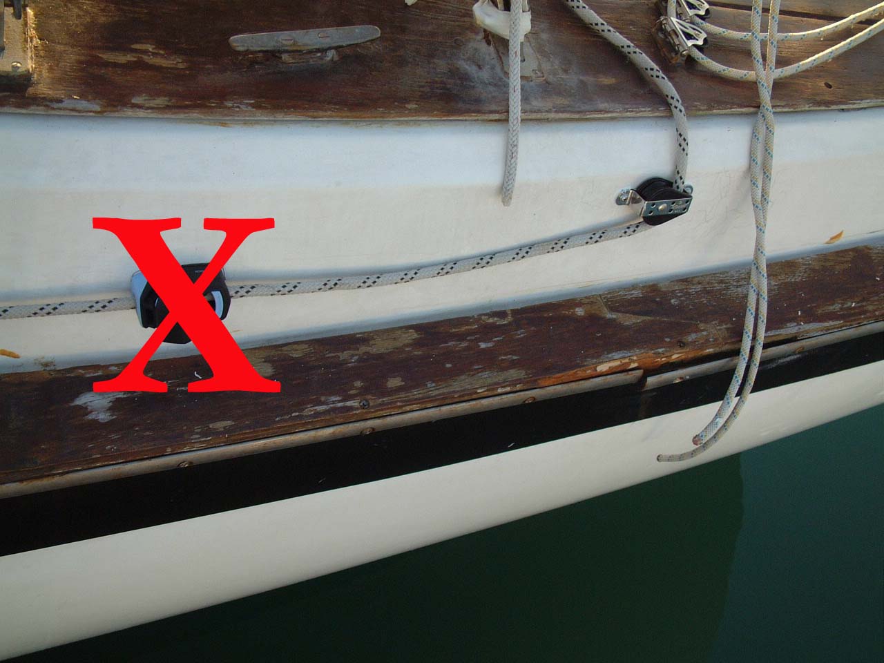 Rope Clutch Did Not Work |
This rope clutch was intended for dinghy sailing and are engineered so that they can be closed and released without actually touching the clutch itself. If you pull back and down on the rope it will release the clutch. If you pull back and up it will close the clutch. This was not apparent to me when I tested it dock side and there was no wind, so there was very little pressure on the furling line. When Chris, Martin and I took Sarah out for a test sail before we departed for Gibraltar the wind was blowing over 15 knots. When Chris tried to let out the furling line under control the clutch kept closing. This is because of the curvature on the coaming where I mounted the clutch and the cheek block the line leads upward relative to the base of the clutch. This effectively created the type of pull on the line that is used to close the clutch. So I had to hold down the clutch mechanism to keep it open, while Chris fed out the furling line and Martin sheeted in the Genoa. Not exactly ideal for my planned single-handed sailing in the Med. |
|
 Furling Line Rope Clutch Is One on the Left |
So I removed the furling line from the clutch and the cheek
block and went back to the old feed from a block on the stanchion base.
It took 6 more years, but I finally implemented a rope clutch on the furling
line as shown on the left and described above. This was implemented at the same time as the rope clutches for the preventer line. The furling line clutch is the one on the left (forward) and the port preventer clutch is the one on the right (aft). |
|
Spinnaker Controls, 2006 |
|
|---|---|
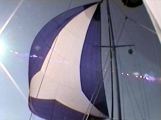 Sarah's Asymmetrical Spinnaker |
The first sail I added to Sarah's inventory after my purchase of the boat was an Asymmetrical Spinnaker from Quantum. I knew at the time the Genoa and Mainsail needed to be replaced as well, but I felt a good down wind, light air sail was the highest priority for the sail inventory before we departed for Bermuda in 2001. As it turned out that was a good choice. We had very light winds all the way from the Chesapeake Bay to Bermuda. Almost all of the sailing we did on that leg was with the Spinnaker. |
|
Since that time I've made little use of the Spinnaker. One of the prime reasons the Spinnaker has stayed in the bag for the last 4 years is the time it takes to set it up and get it flying. It is much easier to just keep the Genoa flying or furl everything and turn on the engine. The process of single-handed setting the Spinnaker (assuming it is already on deck) involved several steps.
After sailing across the Atlantic to Europe without once setting the Spinnaker, I decided it was time to try to simplify and expedite the setting of this sail. This summer (2006) I will be cruising the Mediterranean Sea, and I expect a lot of light winds. Having the Spinnaker back in my sail inventory will likely go a long way to make this sailing a lot more pleasant and productive. As part of this re-working of the Spinnaker set-up, my goal will be to allow the Spinnaker to be set and doused by myself from the cockpit. |
|
| The first simplification I addressed was the running of the downhaul. Not only was this an additional line that had be run down the deck to the cockpit, but there were no provisions on deck or in the cockpit to secure and control this line. Generally I just ran it from the snatch block on bow, down one deck or the other to the cockpit and secured it to whatever cleat might not be in use. That usually was the aft mooring cleat. The downhaul really needed its own cleat and it needed to be fed down the deck so that it was not underfoot and would not foul all of the other lines on deck. | |
My solution is shown on the right. I installed a series of fairleads down the starboard side of the trunk cabin just below the teak eyebrows. Then I installed a small Spinlock rope clutch on the forward end of the cockpit coaming. The rope clutch is far enough forward on the coaming and close enough the side of the trunk cabin to not interfere with anyone going between the cockpit and the deck. It also close enough to the cockpit for it to be an easy reach to open or close the clutch. |
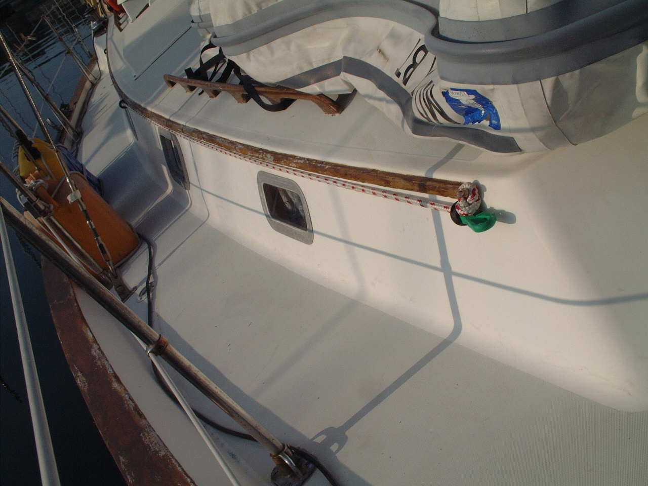 Downhaul Along Cabin Trunk |
 Rope Clutch for Downhaul |
Although the downhaul generally does not handle large forces, I did through-bolt the rope clutch to the coaming. The fairleads were secured to the trunk cabin side with self-taping screws. |
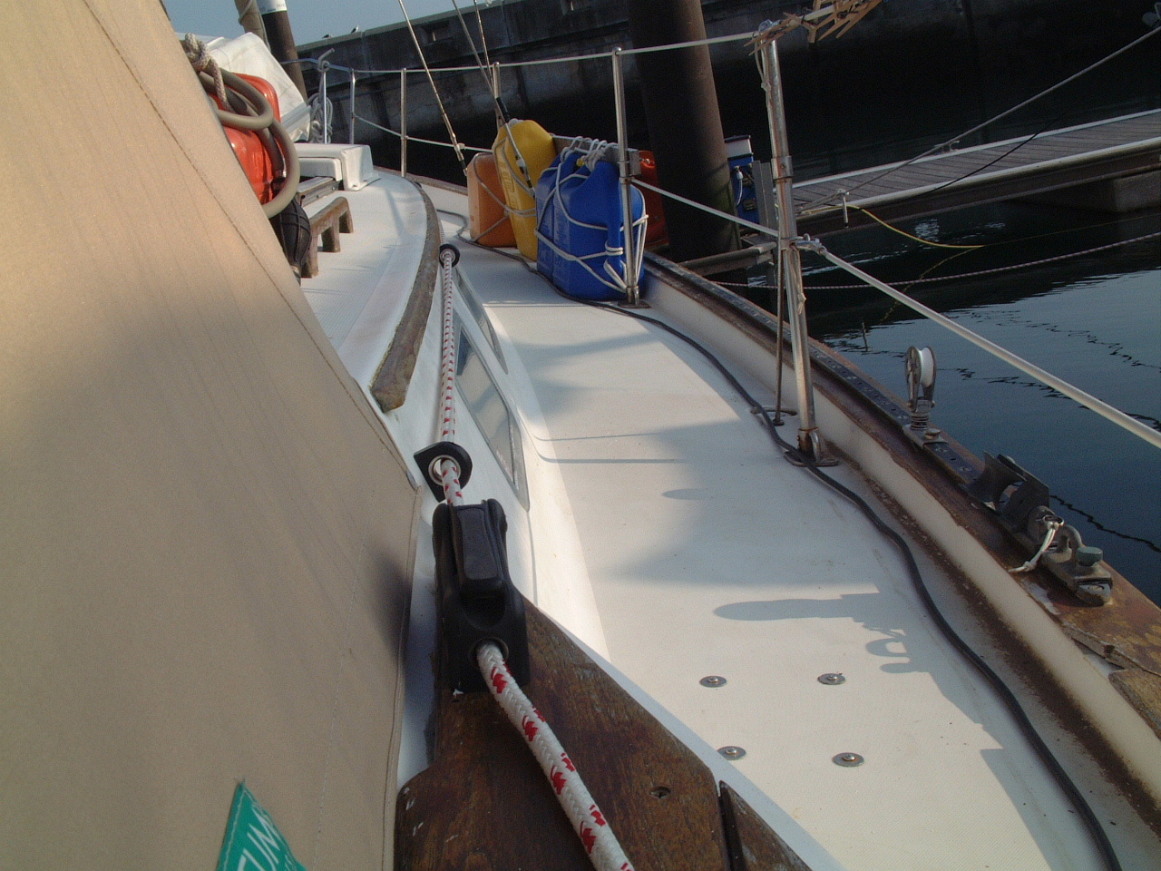
| I leave the downhaul run through the fairleads and the rope clutch at all times. I draw the line tight to the forward fairlead as shown in the picture below. The excess rope tail is coiled and secured to the grab rail, next to the outboard motor gas tank shown in the picture on the right. |
 Fairleads on Cabin Trunk |
| With this arrangement all that is needed to hook up the downhaul is to release the rope clutch and flake the line in the cockpit. Then go forward are pull the line to the bow and clip it to the Tacker cringle and clip the bight of the down haul in the snap shackle at the stem fitting. | |
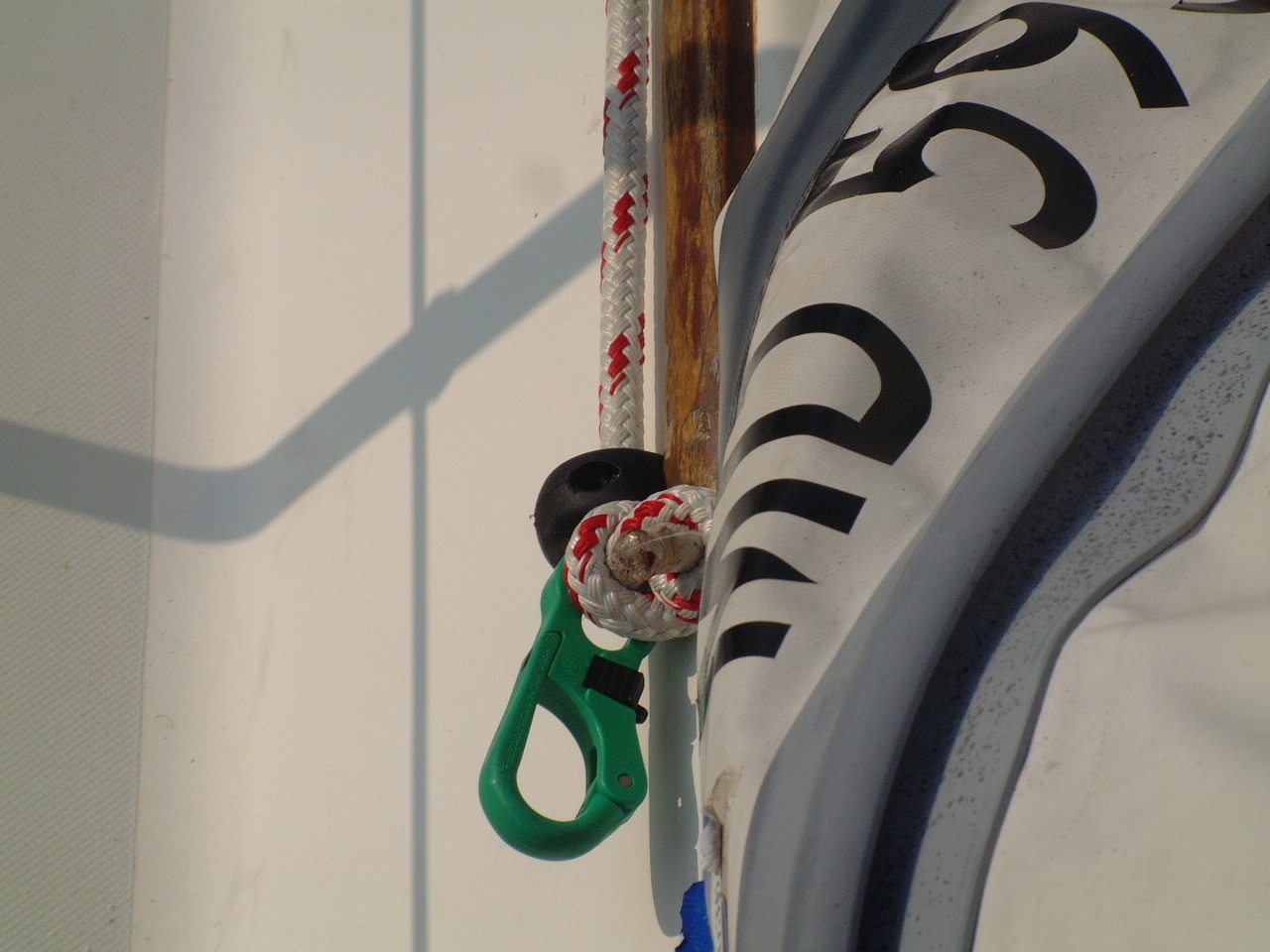 Plastic Snap Shackle for Downhaul |
In the picture on the left I have attached a light duty, plastic snap shackle to the end of the down haul. This shackle was designed as a light air sheet/guy connection to a Spinnaker. I believe it is strong enough for the down haul application. If not I will replace it with a SS snap shackle. Right now it is the the only snap shackle left in my inventory that is either not overkill for the application or clearly not up to the task. So for now, this is my solution. |
| The major issue I can identify with my solution for the downhaul is that the line will run about 6 inches above the foredeck from the stem to the cabin trunk. A real trip line for anyone moving around up there. Normally that person will be me, so if I get tripped by my own design it's only fair. | |
| The next step will be to work the control lines for the ATN
sock back to the cockpit. Currently, I or a crewmember must be on the
foredeck to hoist the Spinnaker sock when we are ready to set the sail.
This is fine when I have at least one other experienced sailor onboard.
However I will be doing some single-handed sailing in the Med, and often
when I have guests on board none of them will have any meaningful sailing
experience. I do not want to put them in the position of working the
spinnaker sock on the fore deck or being at the helm when the spinnaker is
first set. The problem for running the sock halyard back to the cockpit is that it is a continuous line. Both ends of the line are secured to the bottom of the sock. One end goes directly from the sock to the deck and is used to pull the sock down and douse the Spinnaker. The line from the other end runs up inside the sock then down the outside in a sleeve. This end of the line is used to raise the sock and set the spinnaker. You pull the line in one direction to raise the sock and in the other direction to lower the sock. My current plans are to use a double block or two blocks at the base of the mast, one for the line lead to raise the sock and the other for the line lead to lower the sock. Then I will need a cleat somewhere in or near the cockpit to secure this line. It is possible this arrangement will cause me to abandon the ATN-designed single continuous line to raise and lower the sock and go with a separate line for each function. |
|
Once I have implemented the ATN sock control line leads to
the cockpit and have
tested the arrangement, I will set up the
spinnaker on deck in its bag with both sheets run from the sail clew to snatch blocks at the aft end of
the cockpit. At that point the setting of the spinnaker should require only
the following steps.
Although that is nearly the same number of steps as before, they can be accomplished much more quickly with fewer trips between the cockpit and the fore deck. |
|
Dousing the spinnaker should require the following steps.
|
|
| During that 2006 summer in the Med I never did set the Spinnaker even once. I never worked out the sock control line leads so that the Spinnaker could be set and doused from the cockpit. | |
| Deck Tie-Downs, 2004-2012 | |
| I have been using the
Load/Locker Fasteners from
Design Research & Development (DRD) for over seven years to tie items to
the deck or rails. I principally use them to tie my dinghy on the
foredeck and to secure the Bimini. After seven years of constantly being in the elements, the dinghy tie down straps have become stiff and difficult to tighten. I think they can be restored by washing them and maybe soaking them in fabric softener (as I do for my dock lines). |
|
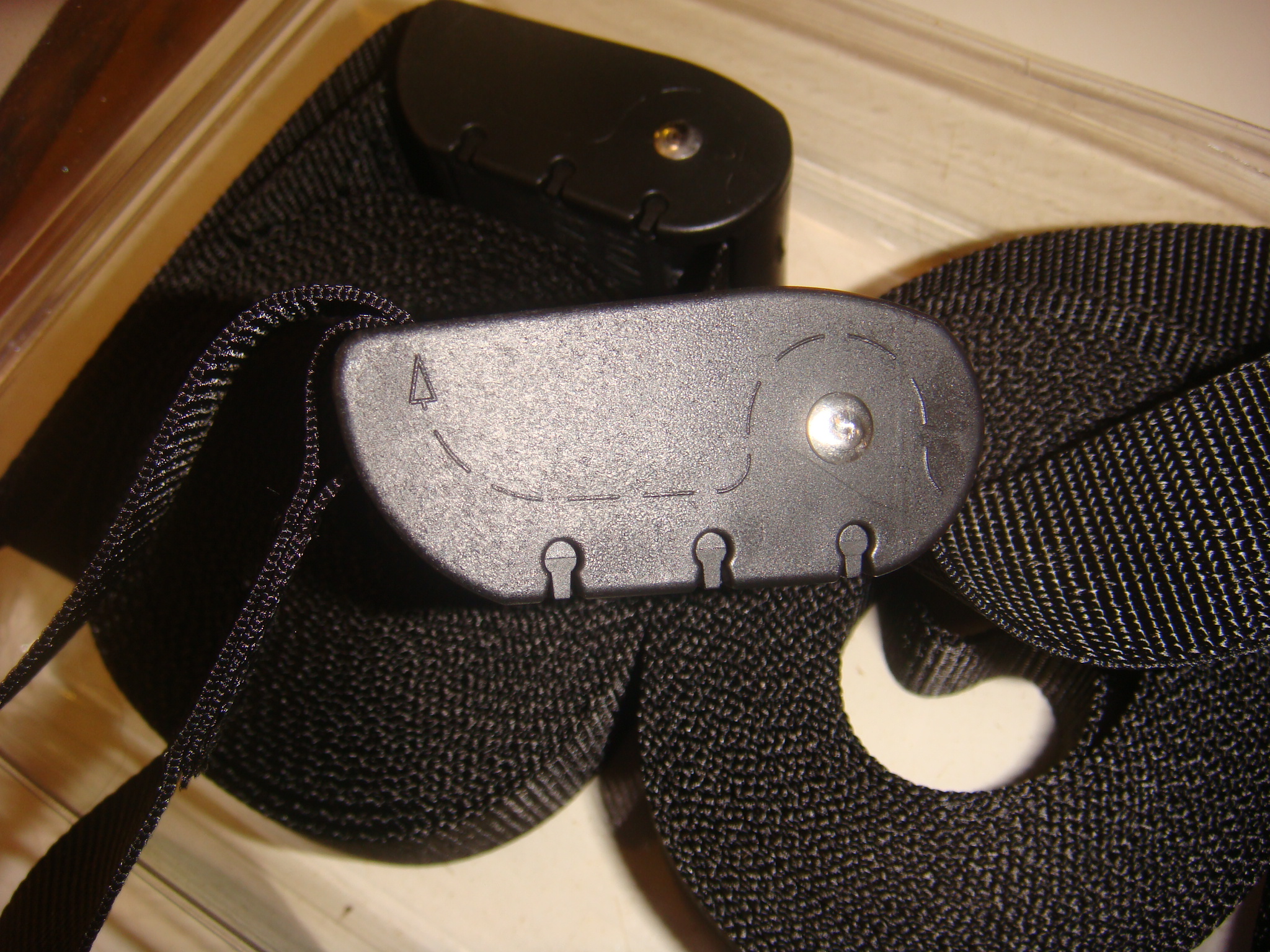 Load/Lock Fasteners from DRD |
However, maybe seven years is enough of a product life for
a relatively inexpensive item, so I ordered another set of fasteners, shown
on the left. This fastener consists of 12' of webbing and a proprietary buckle. The feed path for the webbing is embossed on the side of the buckle. The webbing will slide through the buckle to to tighten and there is a cam in the buckle that keeps the webbing from sliding back. There is also a release button on the buckle that allows the strap to be loosened. |
| On the right is a photo of my AB RIB tied to the
foredeck using two Load/Lock Fasteners. These fasteners make it very easy and quick to loosen the straps and raise the bow of the dinghy to allow the forward cabin hatch to be opened (as shown in the photo). It is equally easy and quick to tightened down the straps when the dinghy has been lowered before getting underway. DRD makes a number of other products that can be used to secure and organize items onboard. |
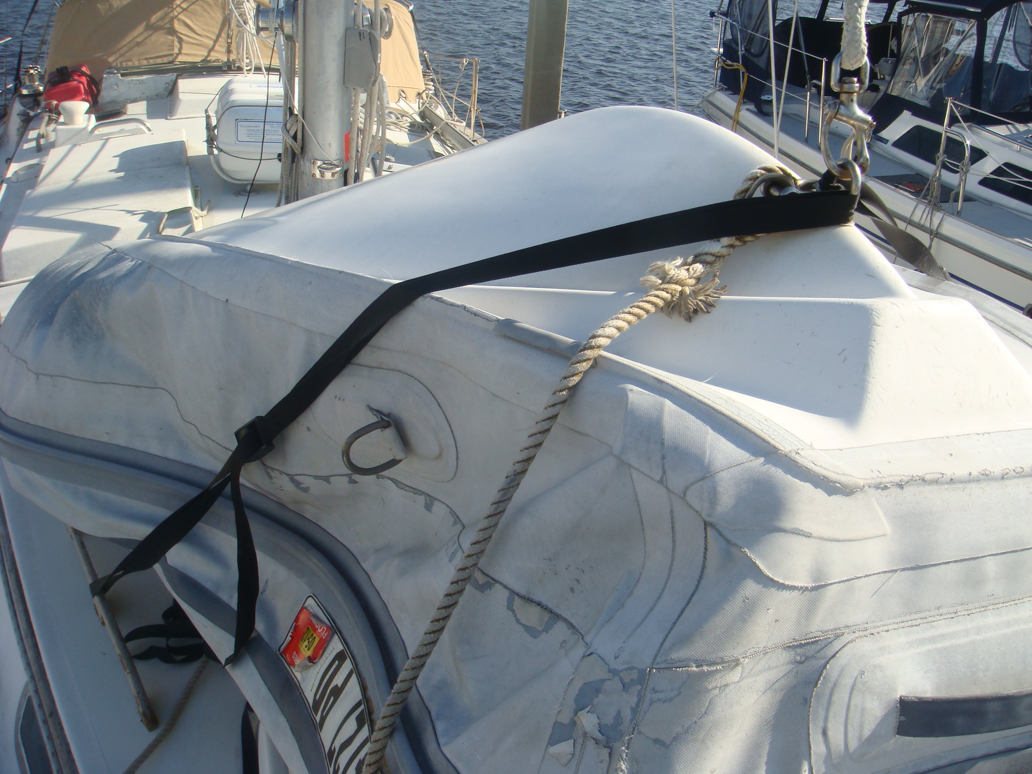 Dinghy Tied Down to the Foredeck |
| Flag Halyard, 2012-2013 | |
| The eye strap on the starboard spreader that supported the flag halyard broke in a storm back in 2009. I did not replace that strap until 2012 when I started thinking about returning to the Bahamas. I would need some place to hoist the Q Flag and the Bahamas Courtesy flag. | |
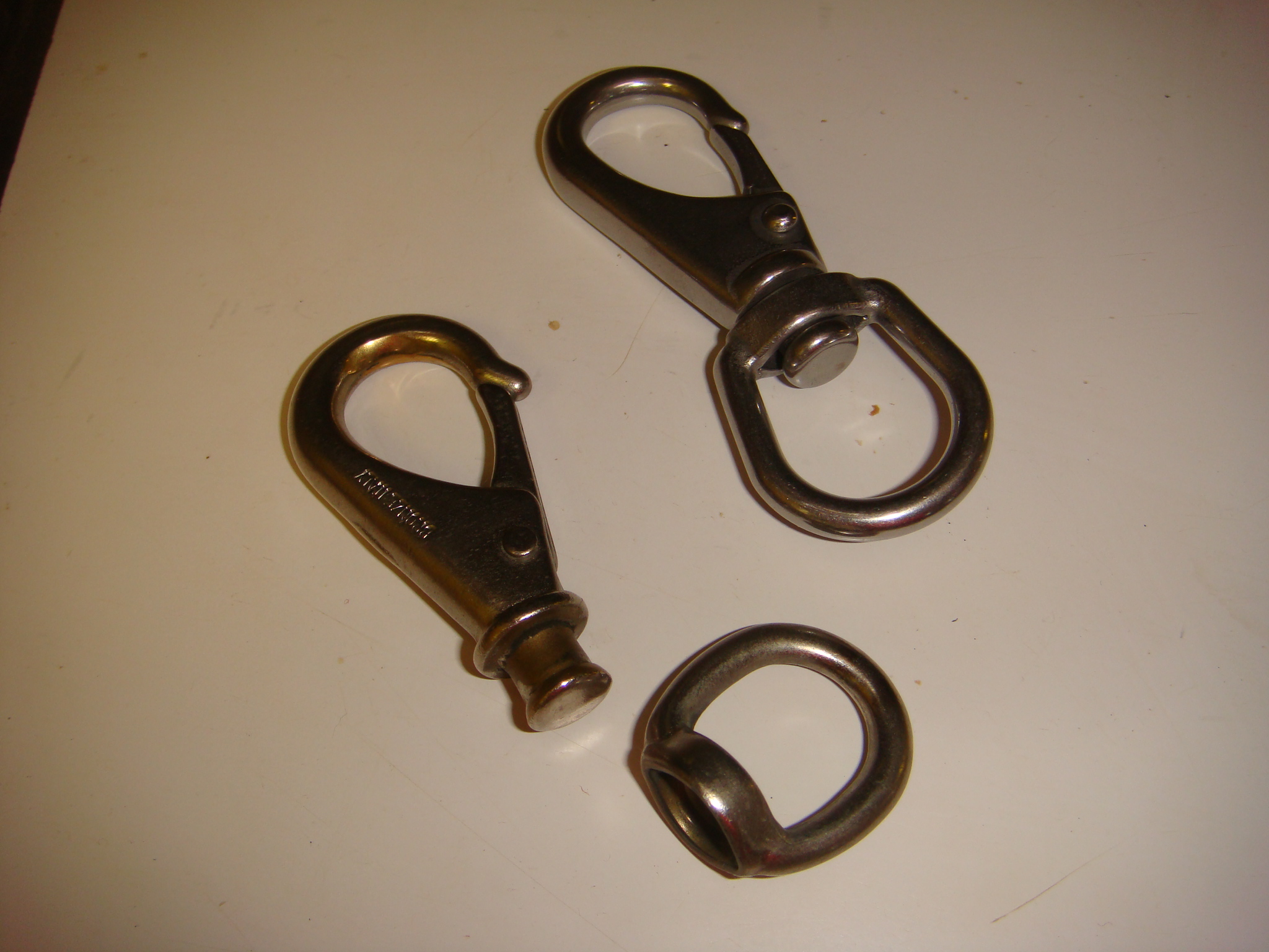 Separated Shackle and Replacement |
When I ran a new halyard I also purchased four shackles from West Marine
to secure two flags.
I then hoisted my SSCA Burgee and felt I was a proper yachtie. A few
weeks later I noticed the burgee was flying from only one shackle. I
discovered that the shackle had pulled loose from the eye base, as shown in
the picture on the left. I thought that must be a defective shackle so I took it back to WM and exchanged it for a new one. A few weeks later I noticed the burgee was again flying on a single shackle. |
| Once more the shackle had separated.
I noticed that the flange that held the shackle to the eye base was beveled
and very slightly larger than the hole in the base. I discovered I
could push the shackle back into the base and work it free. This was
not a defect in a single shackle, but the entire product. I thought I
was buying a SS product, but now it appears the shackle is chromed brass. I purchased replacement SS shackles from Marine Parts Depot. One of those shackles is shown in the picture above. This shackle has a large and un-beveled flange. I replaced the WM shackles with the ones from MPD. Time will only tell, but I do not expect these shackles to shake apart in the next strong wind. The remnants of TS Chantal are expected to pass close to Jacksonville in a few days, so I should have a good test. |
|