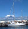
Sailing Vessel (SV) Sarah
Sarah has a new owner as of 7/26/2021. There will be no more updates to these SV Sarah pages
Sarah has a new owner as of 7/26/2021. There will be no more updates to these SV Sarah pages
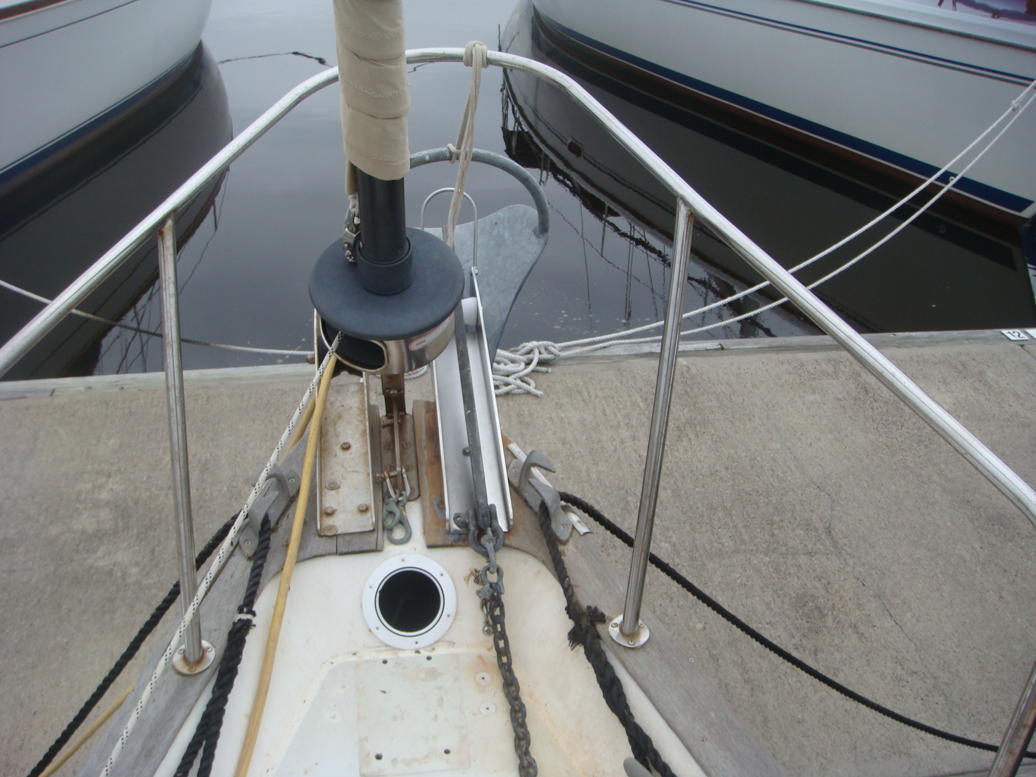
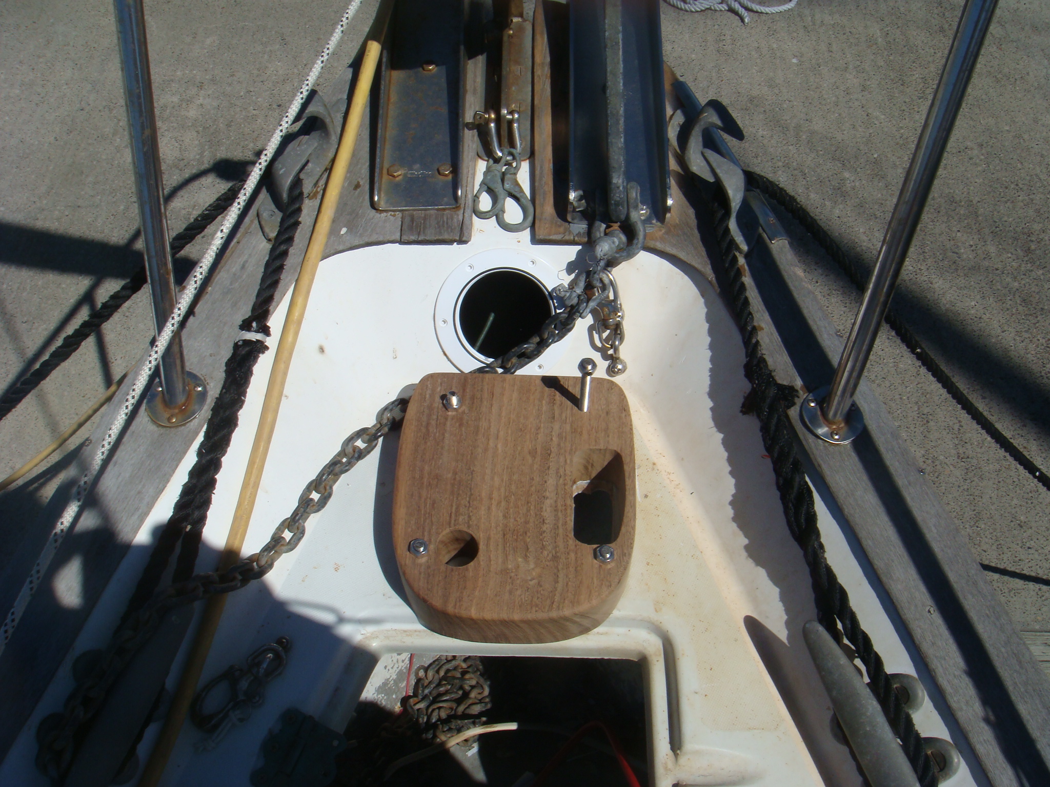
| Sarah came with a Lofrans Royal Manual windlass. While
this is a quality product I discovered that it is a little
undersized for the normal ground tackle on a 42' sailboat.
It was barely adequate for my initial ground tackle - 44 LB
Bruce anchor and 50' of 3/8" chain. Getting the anchor up
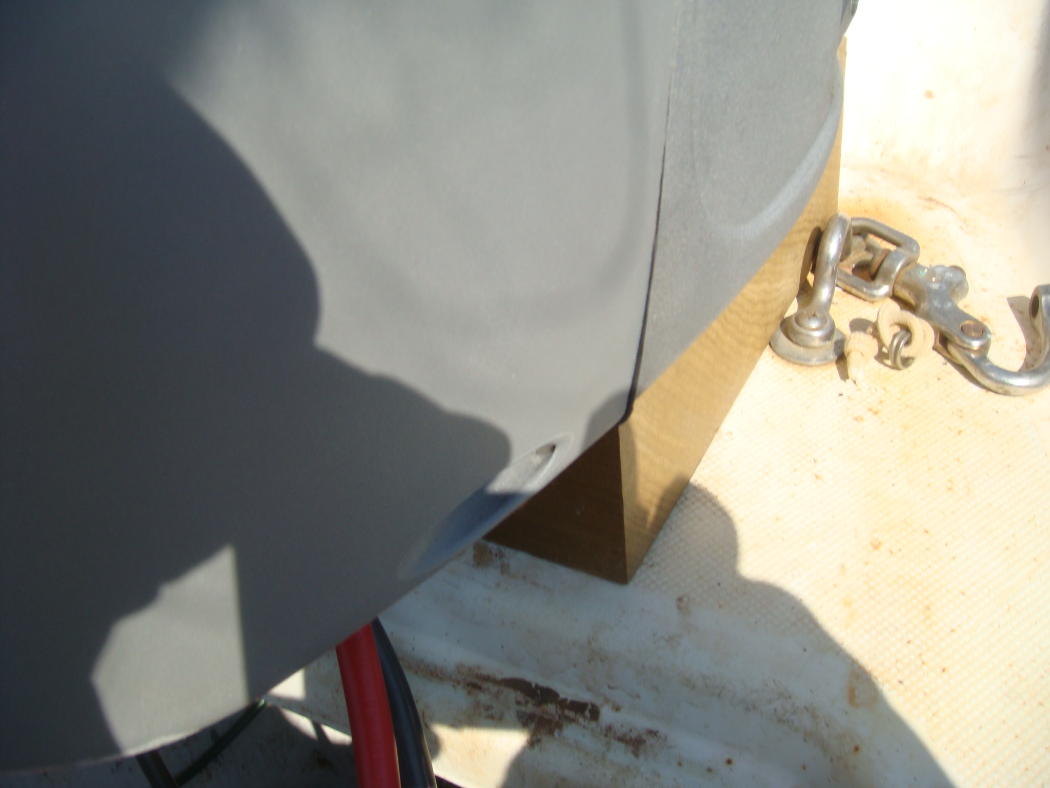
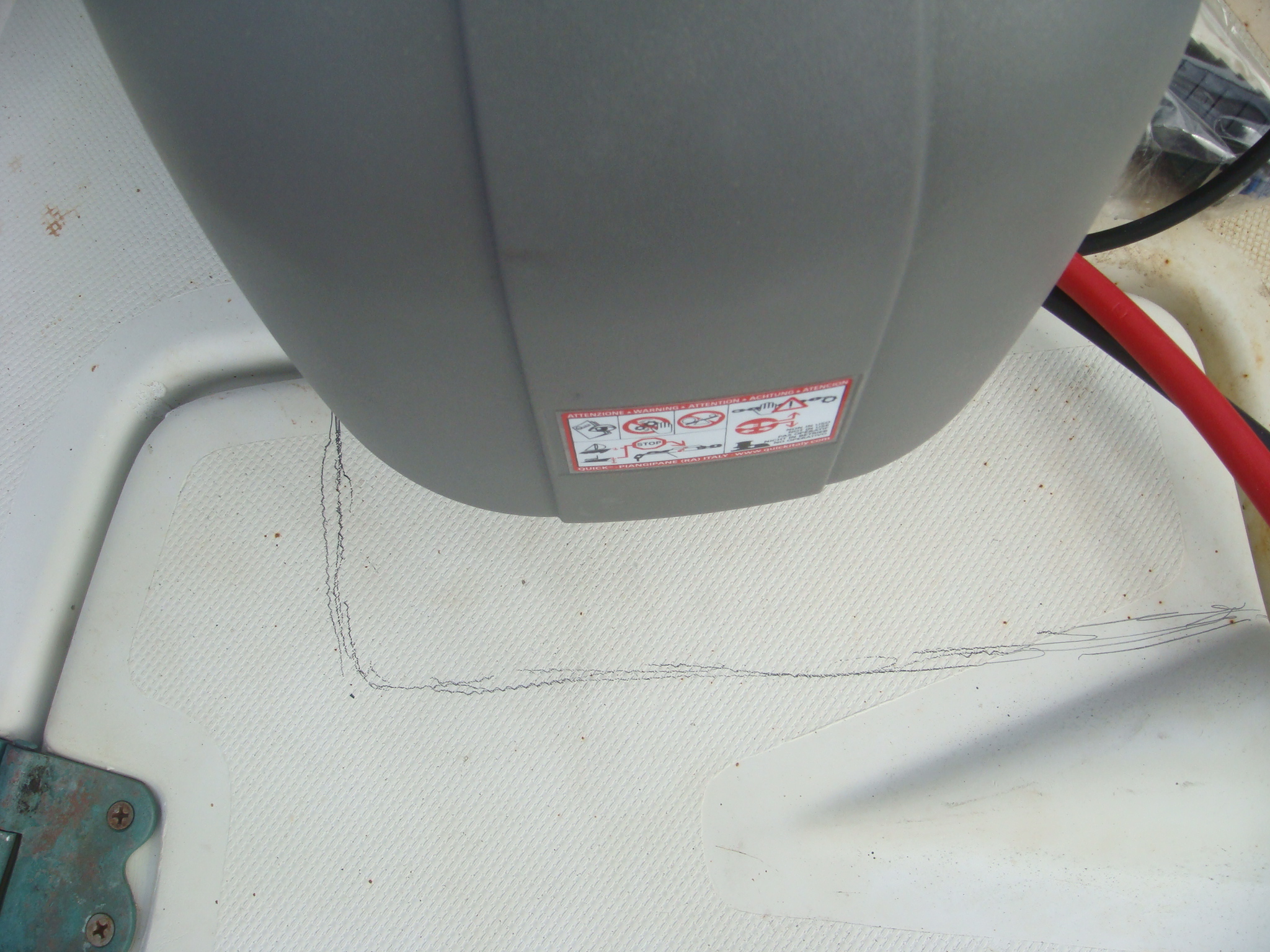
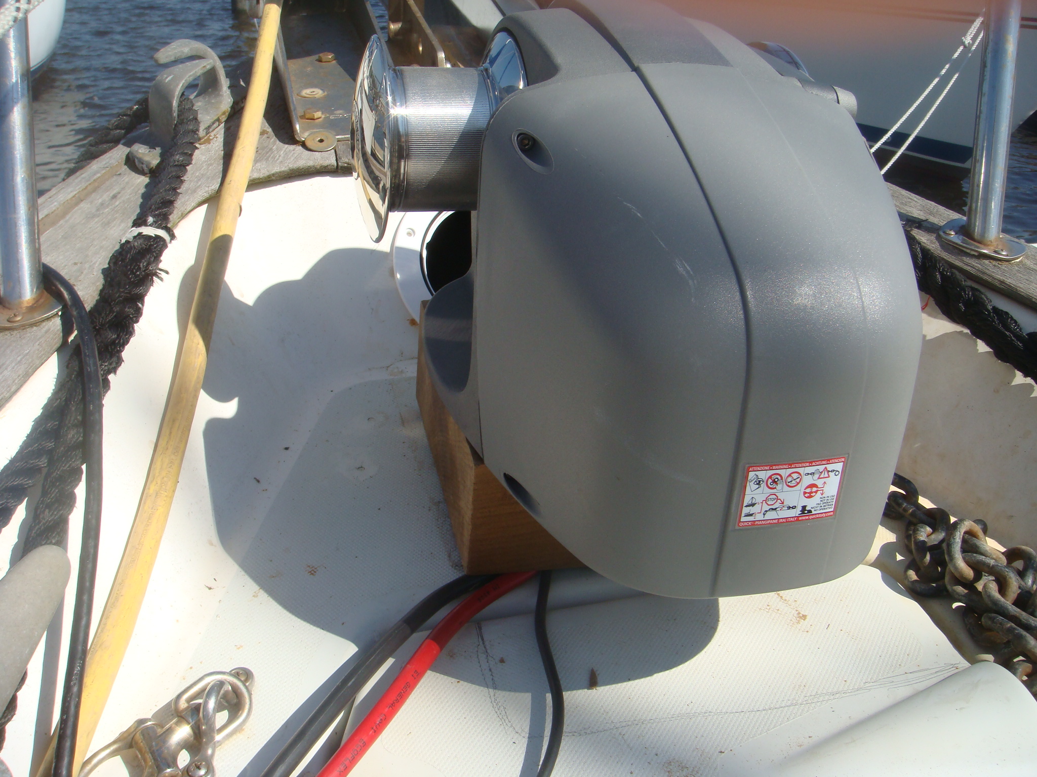
was a PITA, but it got the job done. When I moved to 5/16" all-chain rode and then a 60 LB Manson Supreme anchor the pain got worse. I could normally pull in most of the chain by hand then crank in the last 20' or so. Still that was a lot of work and it took a lot of time at 3-4 links per crank Finally in 2012 I bought a 1500 W Hector windlass by Quick. The first step was to remove the Lofrans windlass as shown on the right. |
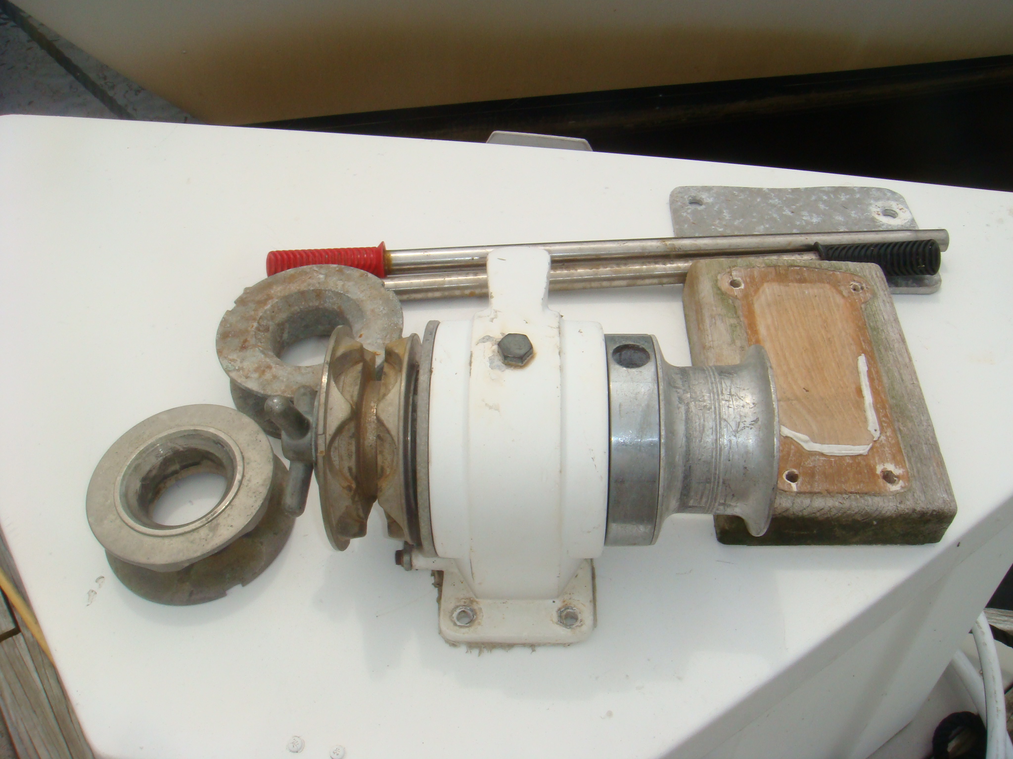 Lofrans Royal Manual Windlass |
| Planning the Winch installation | |
| The Hector windlass has a much larger foot print that the
Royal, largely because of the electric motor. I knew I
would have to do some significant modifications to the deck in
the area of the windlass to install the Hector. First I need to mount the Hector so I can determine what deck modifications would be required. The Royal was mounted on a 2" thick block of teak about 9-3/4" x 6-1/2". |
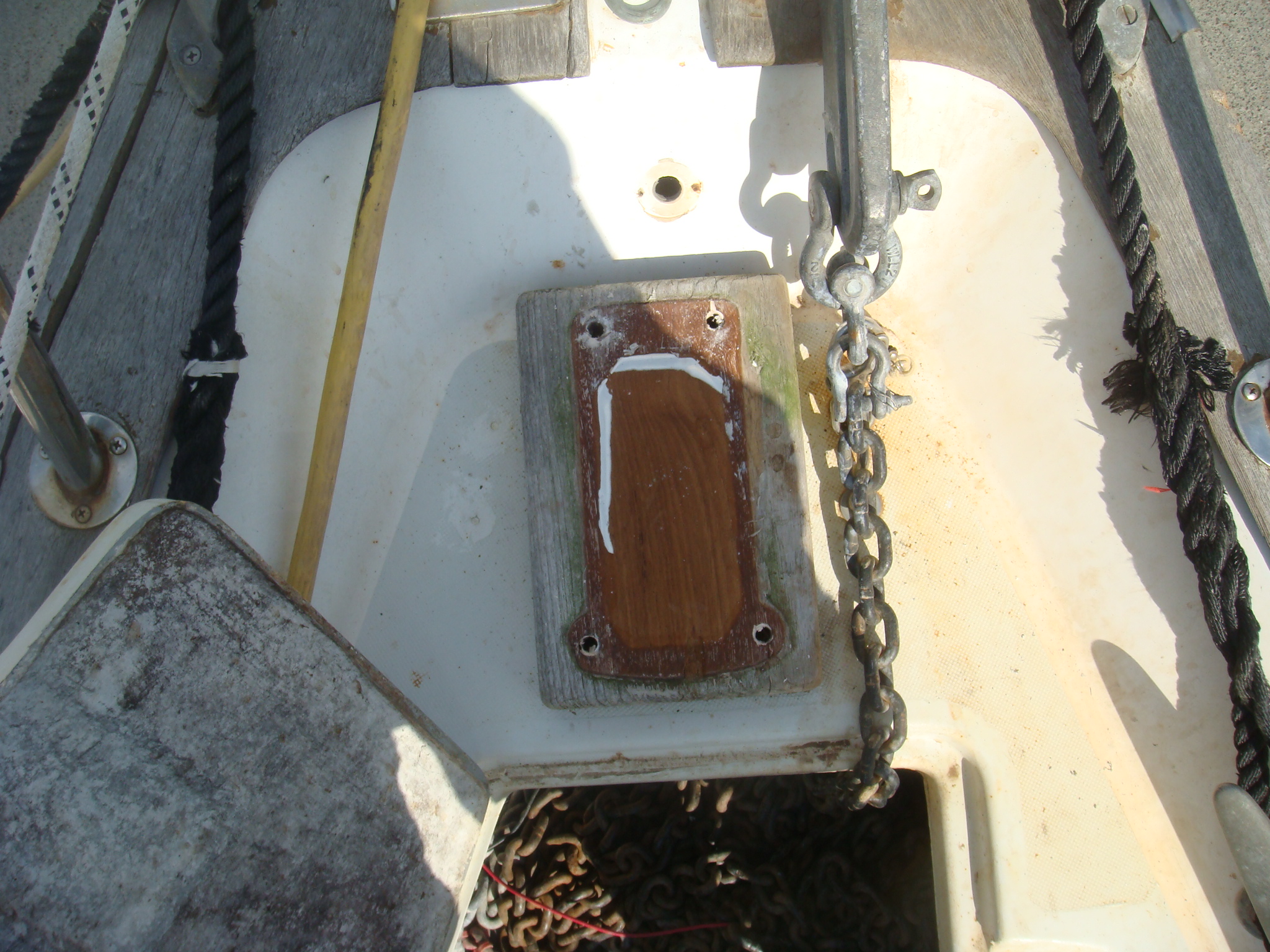 Mounting Block for the Lofrans Royal |
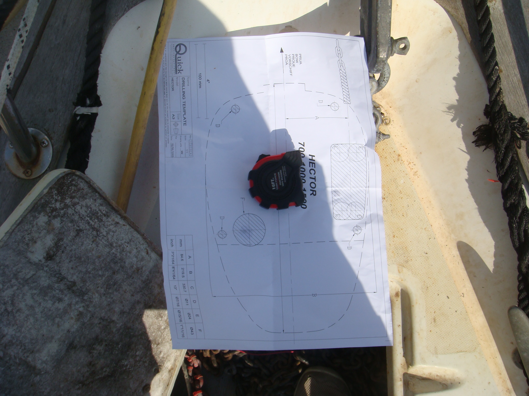 Hector Template On Top of Wood Block |
First I laid the template for the Hector on top of the wood block. It was clear the old block could not be used for the Hector. It was also clear the aft end of the Hector would overlap the on deck anchor well. At a minimum the forward end of the locker hatch would have to be shortened so the hatch could be openned with the Hector in place. |
| I started looking for a suitable piece of wood to replace
block used for the Lofrans. I needed a block at least
8"x8" and 2" or more thick. The thickness is necessary to
insure windlass is high enough such that the chain feed from the
anchor roller to the windlass gypsy was an upward incline.
If there is a downward incline the chain might jump out of the
gypsy. |
 Kauri Block Under the Hector Windlass |
| I finally ordered a block of
Kauri from Woodcraft that is 3" thick. I didn't
know much about Kauri except that is very hard and has been used
in boat building. Kauri comes from New Zealand and most of
the live forests are protected from harvest for lumber.
However thousands of years ago a whole forest for Kauri was
blown down ( earthquake, Tsunami, Typhoon? - nobody knows).
The trees were buried under Peat bogs until they were recently
discovered. These dead trees have been preserved in the
bogs and are now being harvested as a source of hardwood.
My block of wood came from this ancient source of Kauri. The additional 1" of height should provide and upward angle for the chain feed to the windlass gypsy. It will also slightly increase the chain fall from the wheel to the below decks locker. |
|
 Hector Windlass Roughly Positioned on Sarah's Foredeck |
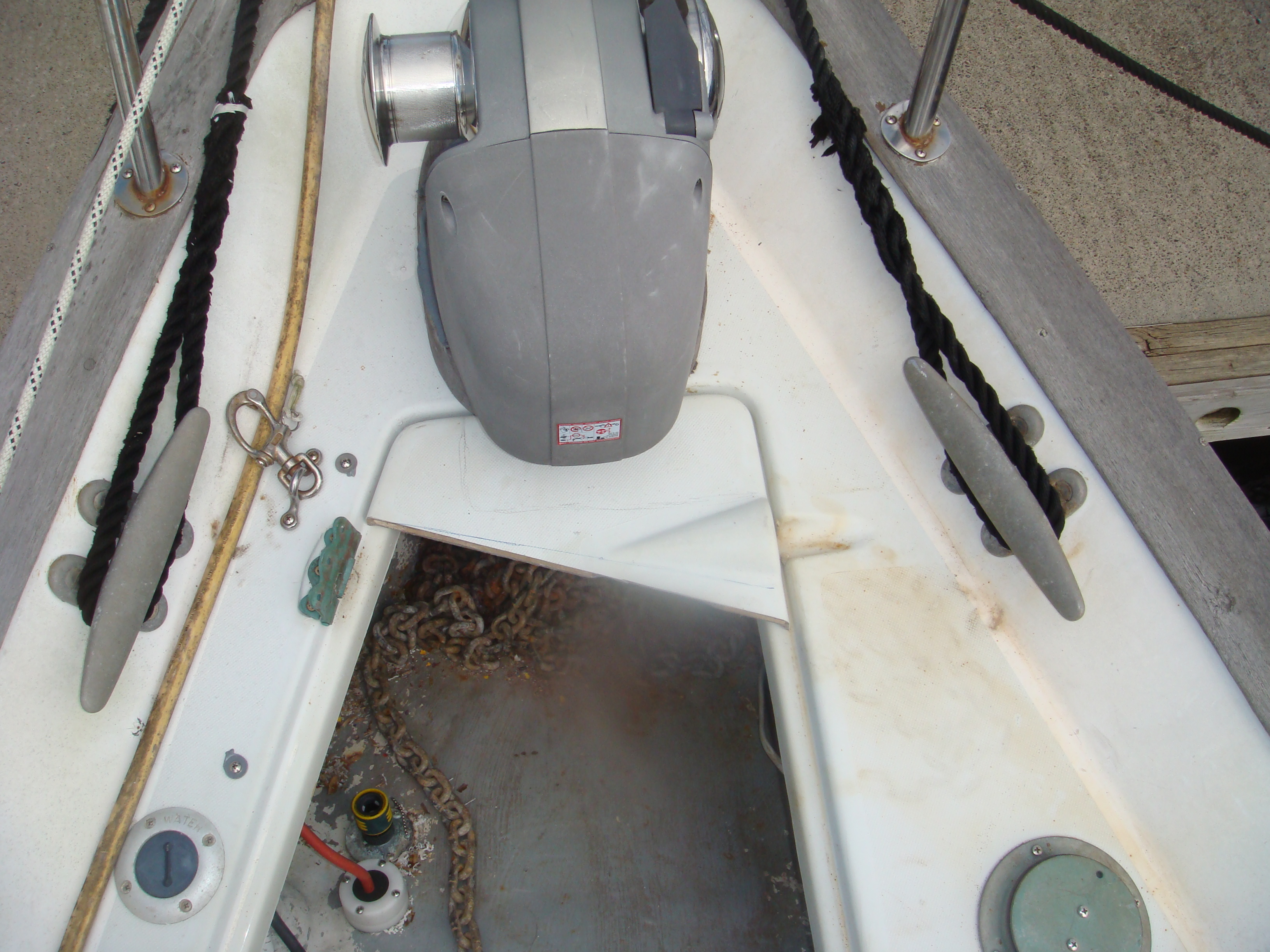
I placed the Kauri block on the deck and then placed the Hector Windlass on top of the block. As you can see in the picture on the left the windlass motor overhangs the anchor locker. At a minimum the locker hatch cover will have to be cut down and the forward section of the locker glassed over. |
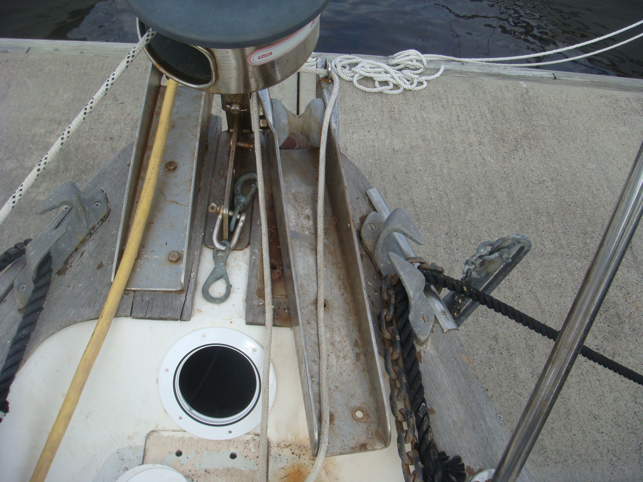
| The windlass does align well with the two anchor rollers.
That is particularly important for the chain wheel on the
starboard side of the windlass. In order for the chain to
feed in and out smoothly the chain must be perpendicular to the
axis of the chain wheel. Perpendicular aligment is
important for the rope winch as well, but it is not as critical
to the Windlass operation. I ordered a new anchor roller for the chain rode. The new roller is about 6" longer than the existing one, which will allow the Manson Supreme anchor to be stored in the roller without overhanging the deck. Until that roller is in place I cannot fix the location of the windlass. |
 Alignment with the Existing Anchor Rollers |
 Doweling Jig to be Used as a Drill Guide |
The first task is to drill the holes in the wood block for the windlass mounting machine bolts. The problem is how to drill the holes perpendicular to the wood block surface without a drill press. After searching the internet for solutions I decided on using a doweling jig, shown in the left. This jig is normally used to drill holes in the edge of a wood piece for dowels. However it provides a wide and level base which I can use as a guide for the drill bit. |
| On of the issues that I knew I had to address was that the
windlass motor housing would overhang the on deck anchor locker.
Several P424 owners have cutout the floor of this locker
and glassed over the deck providing a deep anchor locker.
At this point I am not willing to give up that deck locker.
It is a convenient place to store snubber lines, the deck
washdown hose and other ground tackle items. Also that is
a lot of hard, dirty work. I can cut off the forward end of the hatch, but that might require moving the forward hatch hinge in order for the hatch to swing past the windlass. |
 Overhang on the Anchor Locker Hatch |
 Marking the Tentative Cutout on the Hatch |
In the picture above I have positioned the windlass such
that it would not require the hinge to be moved. However,
when I get the larger anchor roller in place it may be necessary
to move the windlass further aft and require the hinge to be
removed. I wasn't sure how I could do that and still keep
a functional hatch. Then I was browsing the P424 website,
looking at other windlass installations and I found the
solution. I don't need to cut off the entire forward section of the hatch, but just enough to allow the hatch to swing clear of the windlass. In the picture on the left I have marked how the forward section of the hatch could be removed to clear the windlass and still leave the hinge in place. |
| In this case the windlass is far enough forward
that the entire front section of the hatch could be removed and
leave the hinge in place. However if I do move the
windlass aft less than 2" the cutout would include the location
of the hinge. If this ends up the case I can make the
cutout only go 3/4 of the way across the hatch as shown by the
marking. The small section of the hatch remaining on the
forward port side will swing under windlass. The actual modifications to the anchor locker hatch are described further down this page. |
|
| Removing the Old Deck Hardware and Installing the New | |
| After the Lofrans Windlass was removed the next step was to
remove the starboard anchor roller, which will be replaced by a
longer one for the Manson anchor. In order to get access
to the nuts on the machine screws holding the old roller in
place I cut a 4-1/2" access hole in the deck. This hole
will be covered by a screw-on deck plate. In the process of removing the anchor roller I also removed the mounting for the pasarelle I used while in Europe. |
 Passarelle Mount De-Installed |
 Old Anchor Roller De--Installed |
On the left the 5/16" machine screws that held the old anchor roller in place have been removed. |
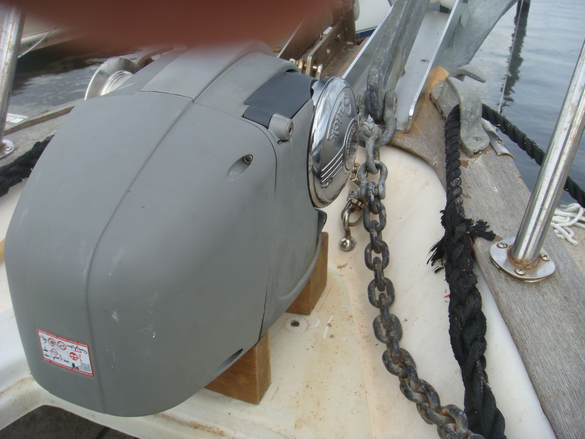
| After filling in the machine screw holes for the old roller with Teak bungs, I installed the new Kingston roller (model QR-30). This roller is 30" long and the entire shank of the anchor sits in the channel of the roller. This roller was designed for 90 LB anchors, so it should be more than strong enough for my 60 LB Manson. |
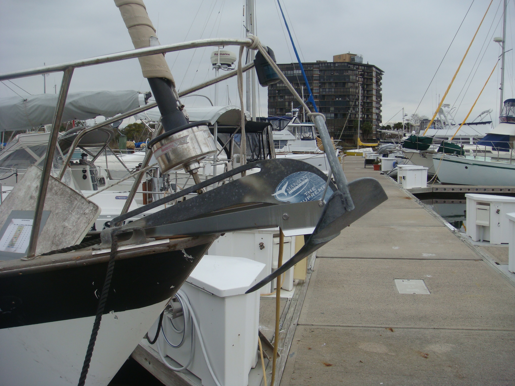 Manson 60 Anchor in the Kingston QR-30 Anchor Roller. |
 The Bale on the Kingston Roller Fits Over the Crown of the Manson Anchor |
When I mounted this roller I set it about 1" further
outboard from the headstay than the previous roller.
Hopefully this will allow the anchor shank to come onboard
without banging into the Harken furler drum. Notice that the large crown on the Manson anchor fits under the bale on the QR-30 roller. This will prevent the anchor lifting out of the roller in rough seas. With the previous roller I had to tie down the crown of the anchor. |
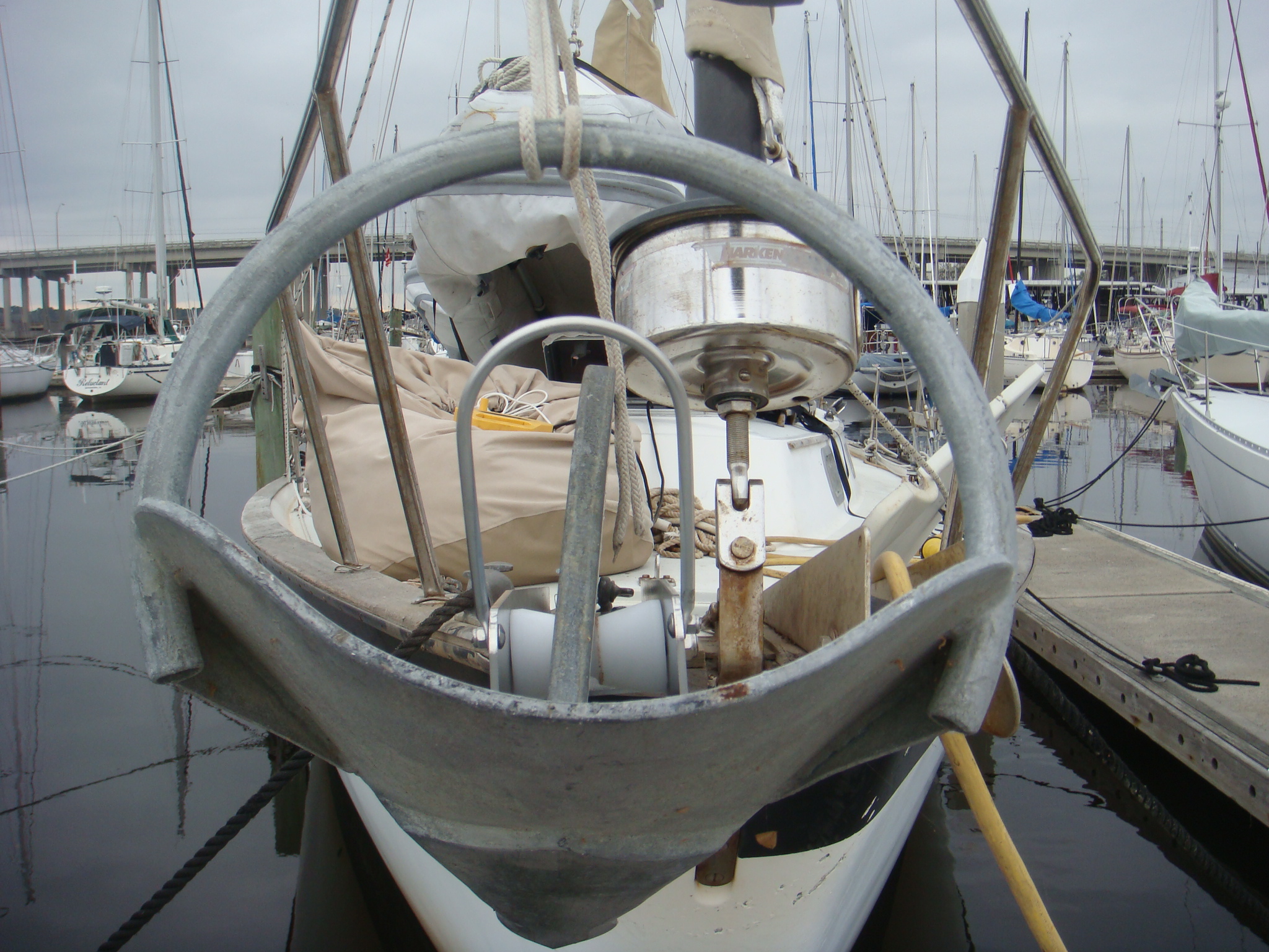
| The view from on deck shows the anchor shank fits completely
within the channel of the roller. With the previous roller
the shank extended more than 4" over the deck, which would
interfere with the windlass location. The anchor is not stable lying on this roller and unless otherwise secured will want to go overboard. This will be a good feature when I use the Quick windlass to release the anchor for a free fall. It does mean I must have a means to secure the anchor when getting underway. |
 View of the Anchor Roller From On Deck |
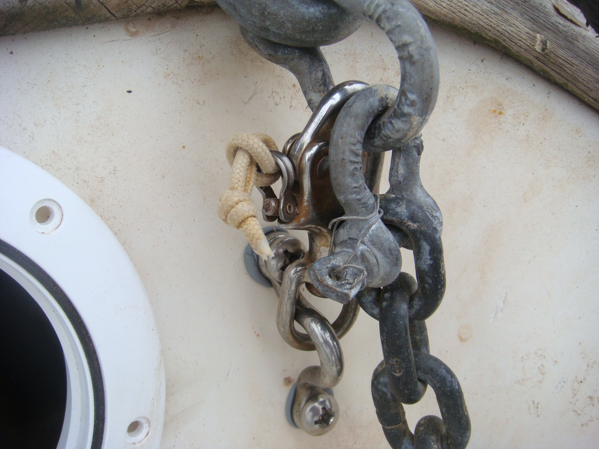 Snap Shackle to Secure the Shank End of the Manson Anchor |
On the left is a close up of the relocated snap shackle that
I use to secure the shank end of the anchor. On the way
off-shore from
Beaufort, NC to Southport, NC this shackle came loose (I
must not have secured it), and the anchor did a lot of cosmetic
damage to the gelcoat on the bow. I think the new position will make it easier for me to secure the shackle and for me to verify that it is secure. |
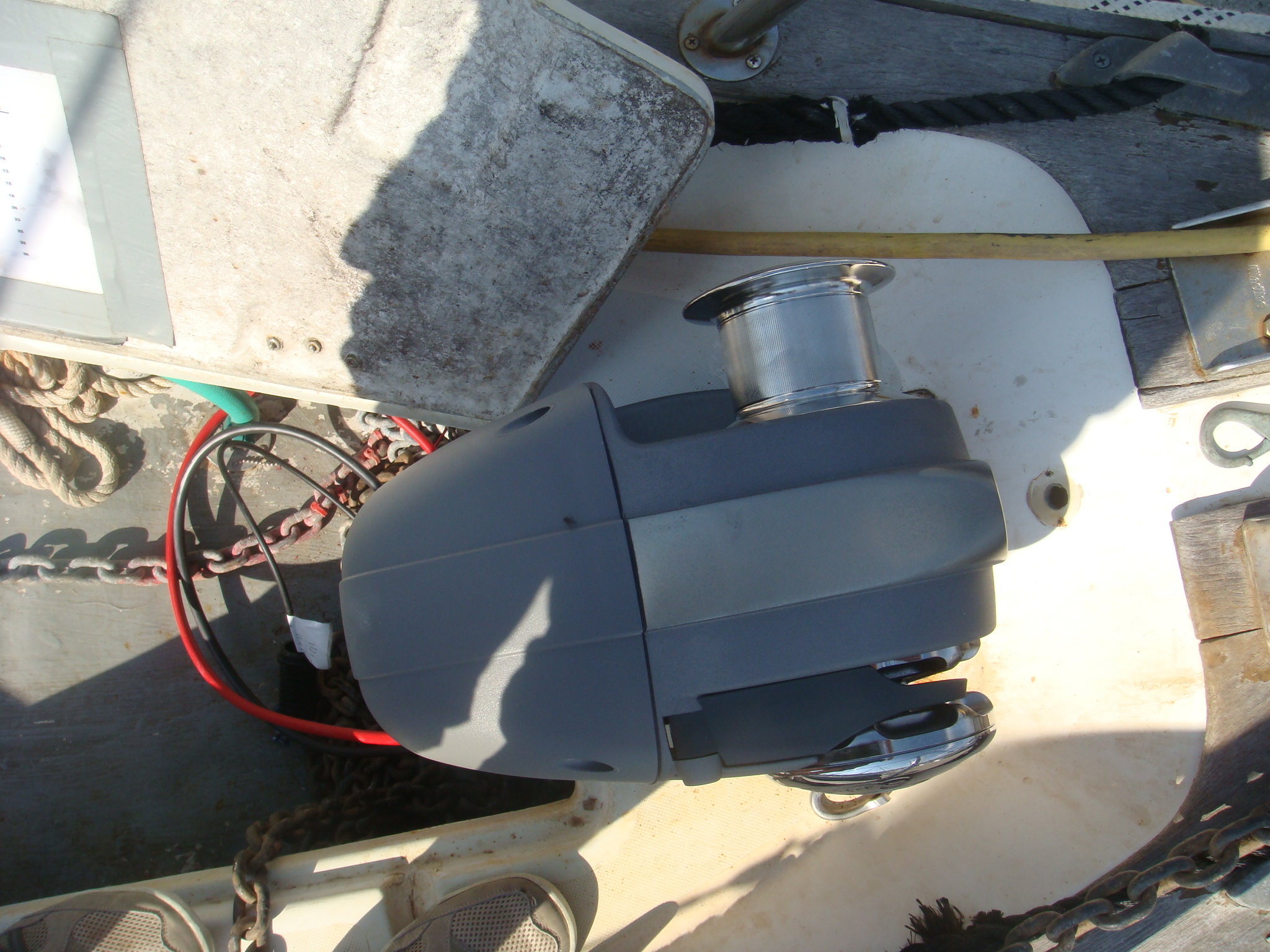
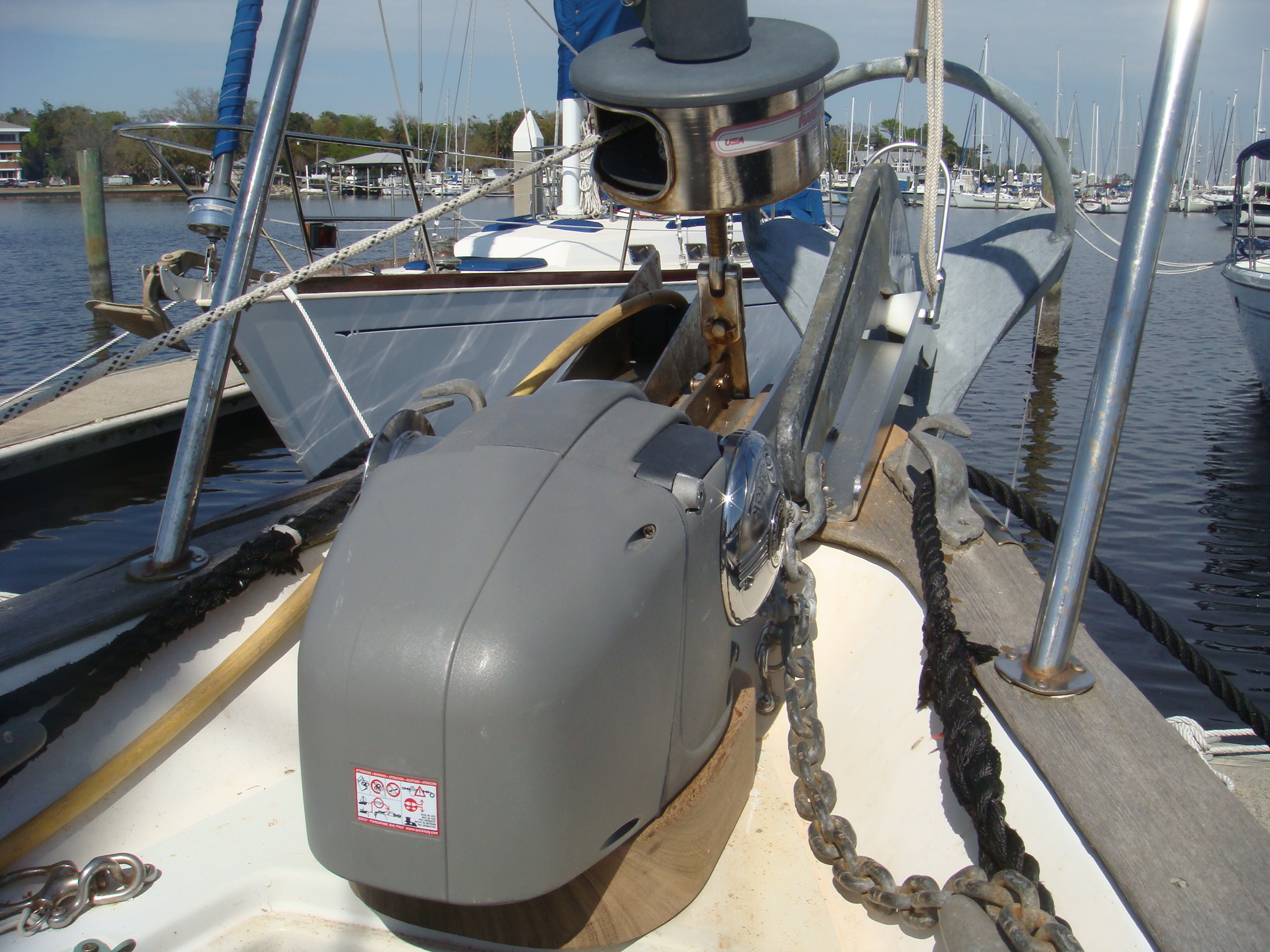
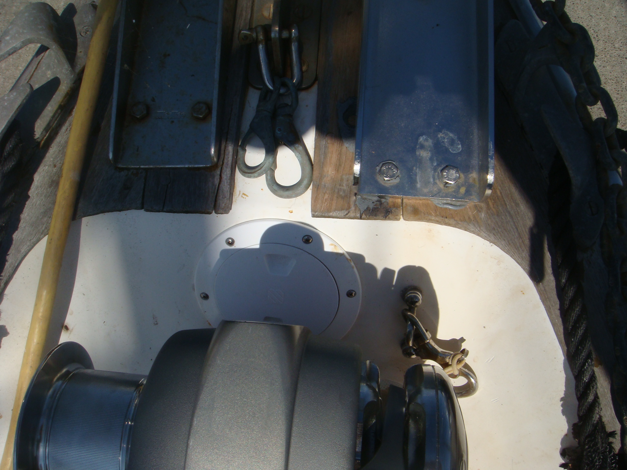
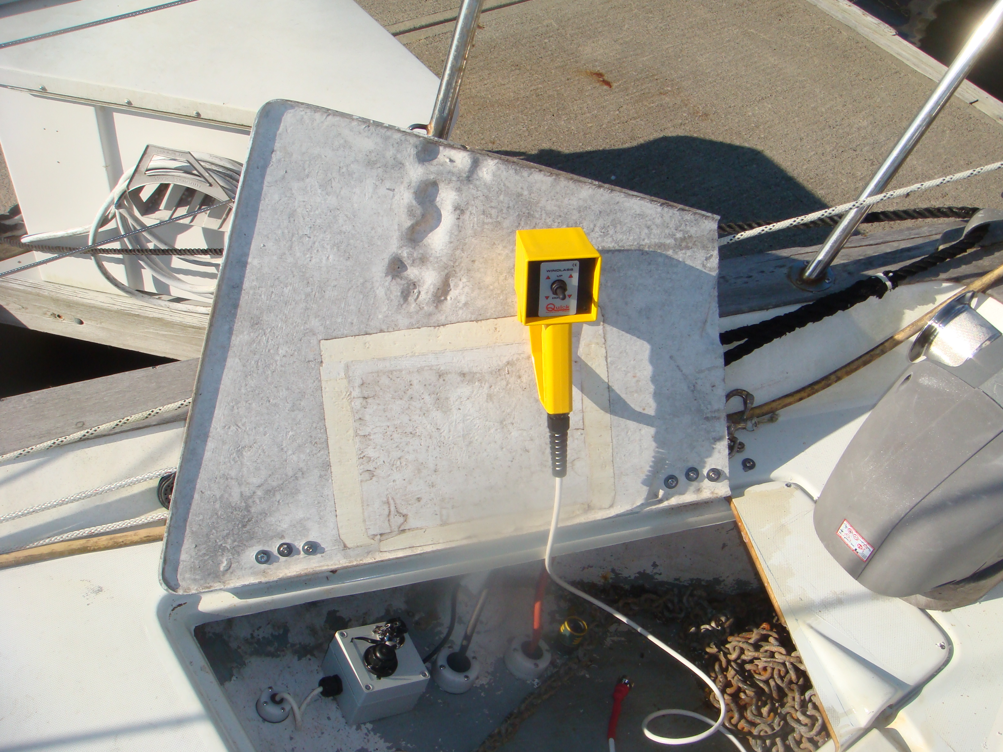
| Setting the Windlass in Position | |
|
With the new anchor roller in place I can now fix the position
of the windlass on deck. In the picture on the right I
have set the windlass on the Kauri mounting block and positioned
it on deck. The windlass is mounted on the four 6" studs,
which have been passed through holes in the mounting block and
the deck, but not secured beneath the deck with nuts. The wiring harness has also been passed through the block and the deck. |
 Windlass Set on Deck |
 Chain Wheel Aligned with New Anchor Roller |
The chain gypsy is aligned with the anchor roller. |
|
The wood mounting block fits the studs that are used to secure
the windlass to the deck, but the motor housing is now
cantelevered above the deck. I may have to insert another
block of wood under the motor housing. That will be done
when I have modified the deck hatch to allow it to open with the
windlass in place. This picture was taken before the holes for the studs and wiring harness were drilled through the deck. |
 Windlass Motor Cantelevered Off the Mounting Block |
 Chain Slot Has Not Been Cut Into Deck |
All of the holes required have been drilled except the slot for
the chain to pass through the deck. After that slot has
been cut I can seal the bottom of the windlass and secure it
with a backing plate and nuts and washers. The side of the chain slot cut into the mounting block will be covered by a 3/4" piece of Kauri. |
| The dry fitting of the windlass on the mounting block exposed a major problem with this block - it is just too small. Although it fit the footprint of the mounting studs the holes required for those studs are too near the edge of the block. There is not enough material between the holes and edge to support the forces placed on the block by the 60 LB windlass. |
 Cracks in the Mounting Block |
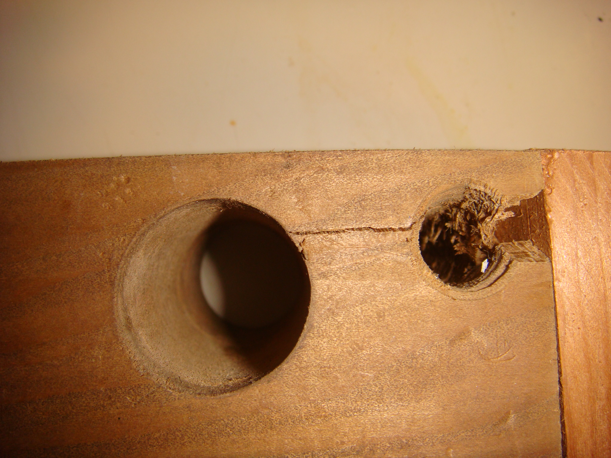 Break in the Wall of a Hole For a Mounting Stud |
In the picture on the left you can see that wall of one stud
hole has broken through to the surface and there is a crack
between this hole and the hole for the electrical cables.
I have screwed a 3/4" thick piece of Kauri to the outside of the
block to cover the break in the block; however it is clear I
need a larger block of wood for this application. Part of the problem is that the mounting holes were not perfectly perpendicular to the surface of the block. The studs bind in the holes. I had to enlarge the holes from 7/16" to 1/2" in order for the studs to pass through the holes. |
|
However the studs still bound against the walls of the holes,
which produced pressure on those holes causing the breaks and
cracks. I need to do two things to complete the mounting of the windlass on deck: |
|
|
|
|
My final solution was to turn the fabricating of a mounting
block to a professional. Jeff Wilder operates a small
woodworking shop near the OYCM, where Sarah is berthed. He
had a large and badly checked block of Ipe (pronounced "eepay"),
but he thought he could get a block large enough for the
windlass from the good section of the block. The result is
shown on the right.
Ipe is a very dense wood used for high-end decking and other
applications requiring strength and durability. Ipe is so
dense that it does not float - it sinks, at least in fresh
water. I have inserted the mounting studs through the block into the holes in the deck that I previously drilled using the old block as my drilling guide. |
 Ipe Mounting Block |
 Hole in Deck for Wiring Will Have to Be Enlarged |
If you look closely you can see that the forward starboard mounting stud will not fit into the deck hole. This is the result of the miss-aligned holes in the old block, not a problem with the new block. I plan to fill the drilled holes with epoxy then re-drill them to seal the deck core. So re-drilling the miss-aligned hole in the deck will not be a problem, nor involve any additional work. |
|
If you look closely at the picture on the left, above, you can
see the hole in the block for the electrical wiring is larger
than the hole in the deck. I drilled the deck hole
undersized, but then discovered that I could not pass the wire
through the hole with terminal lugs attached. I will
re-drill the deck hole to the same size as that in the Ipe
block. Chain Jam: Another problem shown in the picture aove that I did not fix is that the chain slot in the block does not exactly match the slot in the deck. I didn't think that would matter, but in 2014 on the way to the Bahamas I found the chain would jam up in the slot when continuously taking in chain. I found I had to pulse the windlass taking in a couple of feet then pausing for a second to insure the chain fell through the deck without jamming. Once I figured this out it was not a major problem as I had to also pause periodically to knock down any chain castle in the locker anyway. |
|
|
I re-drilled the forward starboard mounting hole in the deck
using a 7/16" bit and the wood block as my drill guide.
The hole for the wiring is supposed by 1-9/16", which is the
size of the hole in the block. I could not find a Forstner
bit or hole saw of that size, so I used a 1-1/2" Forstner bit to
enlarge the hole in the deck for the wiring. Then I dry-fitted the windlass, studs and block on the deck. |
 Windlass Dry-Fitted on Ipe Block |
 Another View of Dry-Fit |
Now everything fits properly. The next step is to fill all of the mounting holes with epoxy to seal the walls and provide a solid deck core to accept the compression load of the mounting studs and nuts. The larger holes for the wiring and the chain will not have the same level of compression force and I will just seal the walls of those holes with epoxy, rather than fill them and re-drill the holes. |
|
After verifying the fit for the deck holes, I removed the
windlass and block and then sealed the holes with epoxy.
For the wiring harness hole and the chain slot I just painted
the exposed core with epoxy. For the holes for the
mounting screws I filled them with epoxy thickened with
Coloidial Silica, The bottoms of all the holes were sealed
with Gorilla Tape to prevent the epoxy from dripping through
into the anchor well. Once the epoxy in the wiring hole and chain slot sets I will add at least one more coat. |
 Decks Sealed With Epoxy |
 Windlass Remounted After Re-Drilling the Mounting Holes |
Two days later I re-drilled the holes and re-mounted the windlass on the block and the deck. I still have to secure the studs under the deck. |
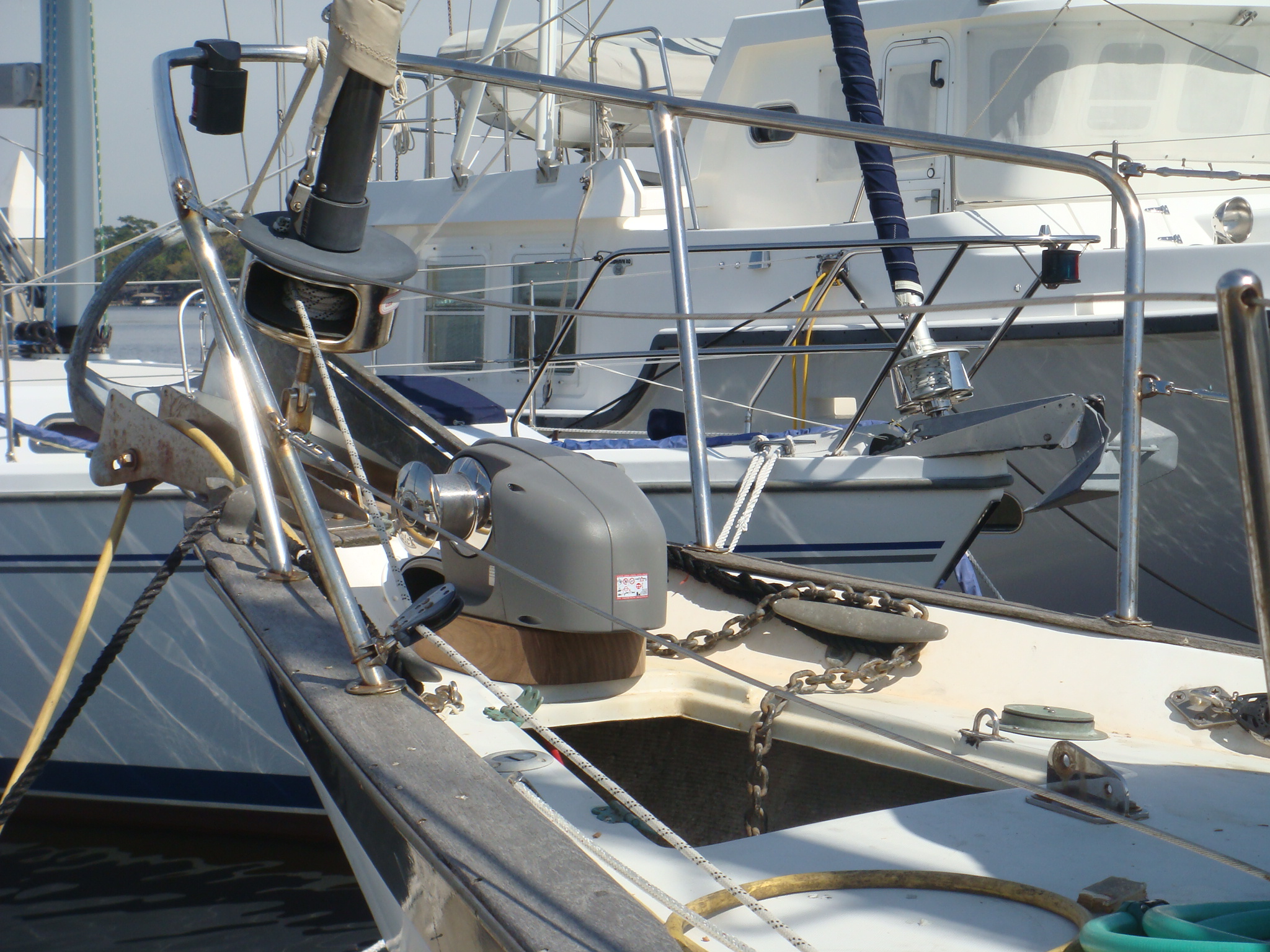
| Before the windlass was mounted I installed the deck plate that covers the opening to stem section of the bow. |
 Deck Plate for Access to Stem |
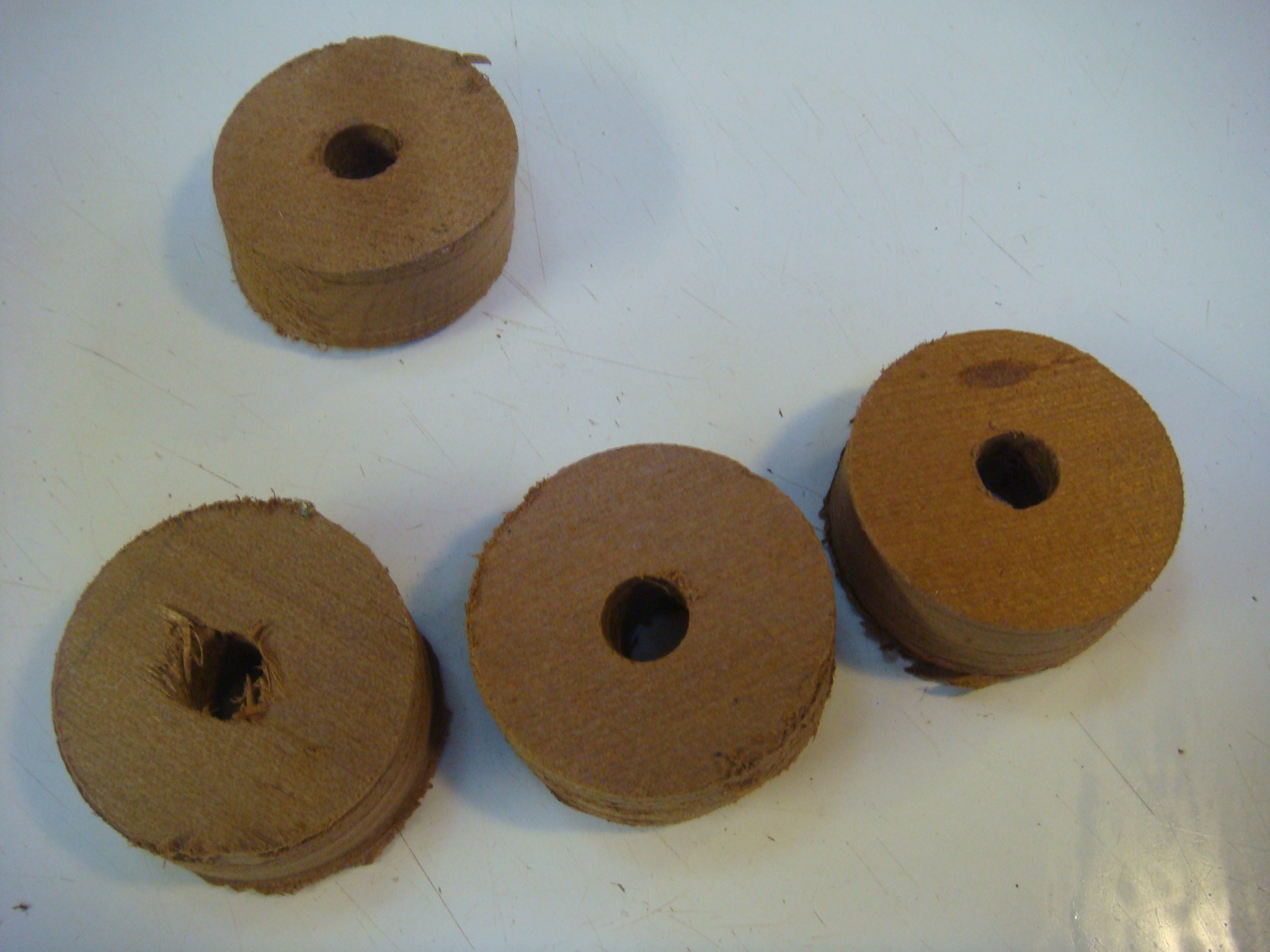 Kauri Wood Fender Washers |
I had planned to make a backing plate of aluminum, but the large cutouts in the deck for the chain slot and wiring harness makes that somewhate impractical. Instead I made 1-1/2" diameter fender washers out of my scrap pieces of Kauri as shown on the left. |
|
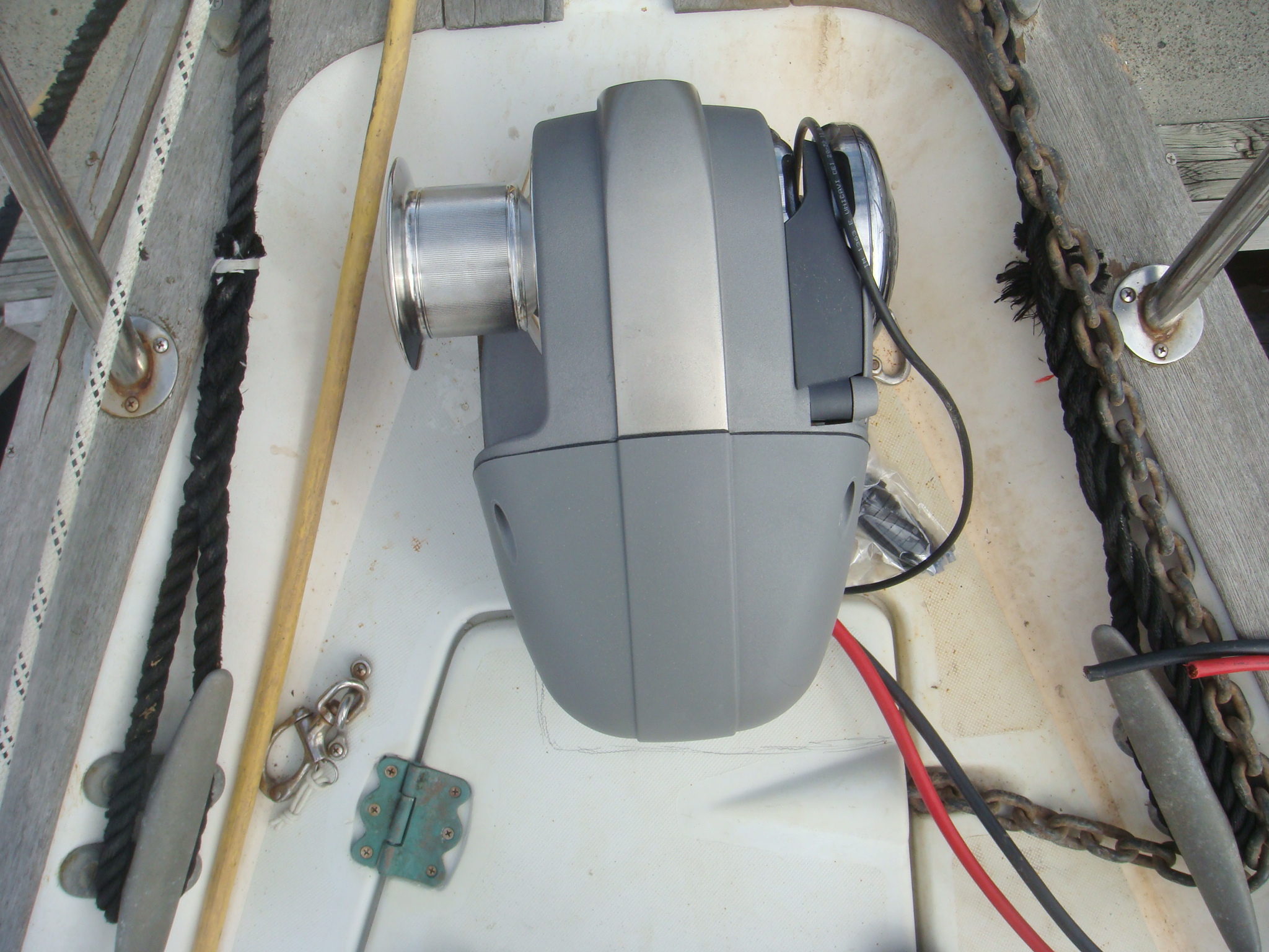
I thought I was home free
with the deck mounting. The wooden fender washers seemed
to work fine. They also produced just enough filler that a
17mm deep socket could tighten the nuts on all of the studs but
one. Although I couldn't see clear under the deck I could feel that the port foward stud penetrated the deck much deeper that the other studs. The depth of the stud under the deck was too deep for my socket. I took the picture on the right to confirm what I felt. When I inserted the studs into the base I had great difficulty getting the last stud to engage the threads on the housing. I thought I finally got it to engage but could not get it to thread fully into the housing. I figured that when I started to tighten the nut it would draw the stud up into the housing. It appears that the process of getting the studs to feed through the deck caused the problem stud to back off the threads. |
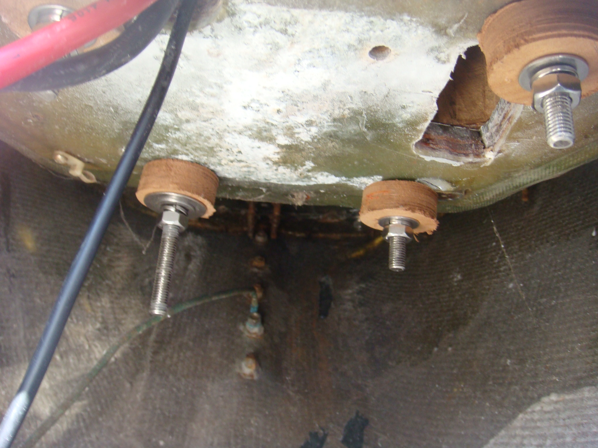 Forward Port Stud Not Threaded Into Windlass Housing |
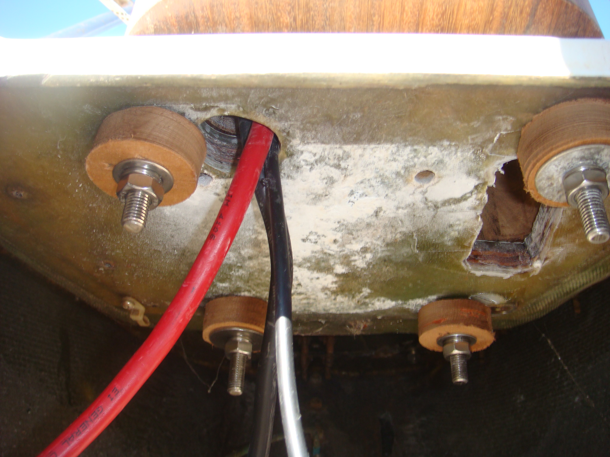 Forward Port Stud Re-Threaded Into Housing |
So I had to completely remove the windlass from the deck.
Sure enough that problem stud was disconnected from the
windlass. The hole in the mounting block is very slightly
miss-aligned with the threaded hole on the windlass frame, which it made it very difficult to
make the stud threads engage those in the windlass housing.
Once engaged the stud threads tended to dis-engage when turned
further. Finally by backing the block off the other studs about 1" I had enough wiggle room to get the stud threads fully engaged. This time I used the nut to draw the stud further into the housing threads before re-mounting the windlass on deck. |
| Now I believe the mounting project is complete and I can concentrate on the electrical installation. | |
| Planning the Electrical Installation | |
|
The most significant decision in the electrical installation of the windlass is which battery bank will supply the power. For the installation on Sarah I have three choices.
The first two choices involve a long cable run to windlass in the bow. In the case of the House bank that run could be over 100' (50' each for the positive and negative cables). With a nominal load of 100A that run would require 1/0 AWG cable. A battery in the bow would significantly reduce the cable size as it would only have to carry a charging circuit (20A or more). However, the windlass is going add a lot of weight to the bow and a Group 31 battery would add even more weight. Also I would have no backup for the windlass battery in the bow. With options 1 and 2 I can use my battery switches to have the alernate bank take up the load. I decided not to go with the bow battery bank, but I hadn't decided whether the House or Start bank will provide the power for the windlass. The installation manual for the Remote Chain Counter I purchased with the windlass warns to not connect the chain counter and the windlass to the same battery bank. I assume this to avoid a major voltage drop at the counter when the windlass motor starts up. This is the reason I separated the House and Start banks in the first place to avoid a voltage drop at the electronics when starting the engine. This requirement would be best supported by the bow battery bank, but I really don't want to go that way. My initial thinking was to use the Start battery for the windlass motor and the House bank for the counter. The Start battery is only a Group 24, which would not have sufficient capacity for anything other than brief operation of the windlass. However, I will almost always be running the engine when I run the windlass, so most of the power will be coming from the engine alternator. In the unlikely event where I need to run the windlass without the engine running I can use my battery switches to power the windlass from the House bank. I discussed these options with the Quick technical support manager he recommended against using the Start battery because of its low capacity. He said the voltage drop from the windlass motor, given my use of 1/0 AWG cable, would be minimal. The real concern is signal noise from the motor in the power going to the chain counter. So I have changed my plan to use the House bank to power the windlass motor as well as the chain counter. Hopefully ferrites on the chain counter power will minimize the effect of noise from the windlass. I will have to finally modify the alternator wiring on the Yanmar engine and the battery combiner to provide charging current to the House bank before the Start battery. |
|
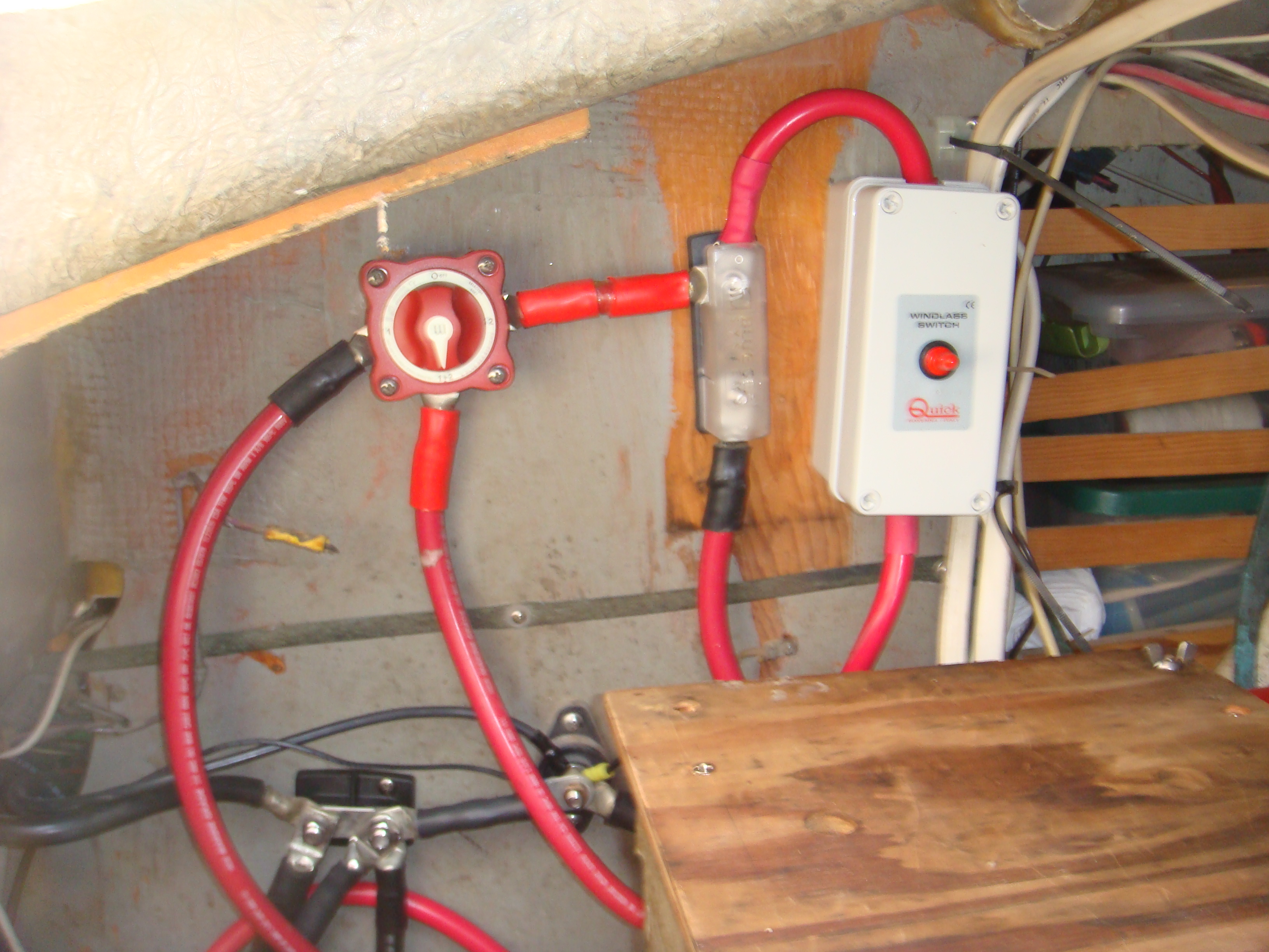 100 A Circuit Breaker in a FIBOX Enclosure Mounted on Bulkhead in Starboard Cockpit Locker |
Quick provided a 100A Hydraulic-Magnetic circuit breaker for the power to the windlass, but I needed
to come up with a place to mount it. Given I will be using
1/0 cable, mounting the breaker on the main electric panel is
not an option. Instead I put the breaker in a FIBOX electrical enclosure purchased from McMaster-Carr. This box is mounted in the starboard cockpit locker next to the battery selector switch for the house batteries, as shown on the left. |
|
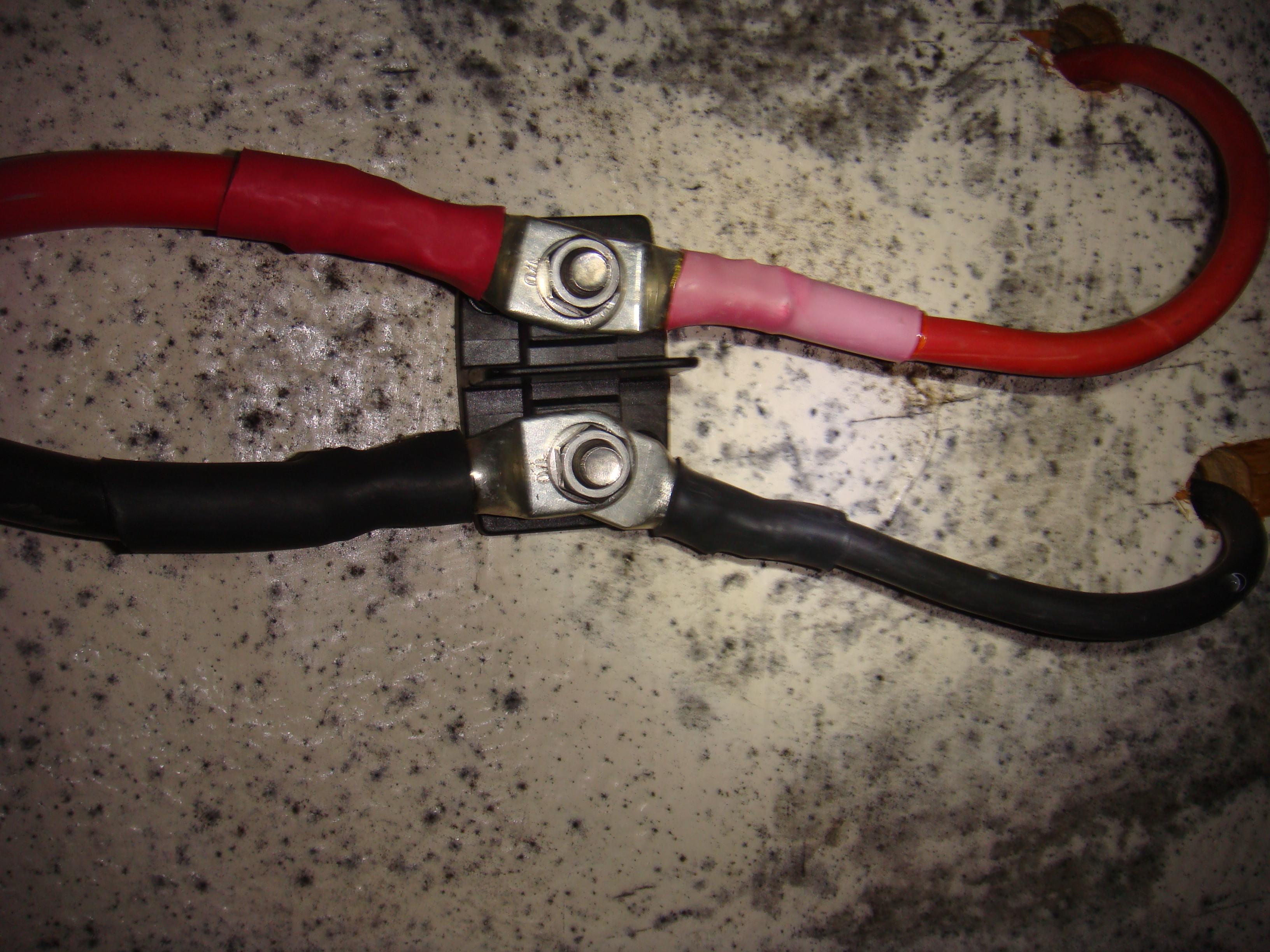
One other electrical modification was necessary. All of
the negative battery cables (2 house and 1 Start) plus a few
other cables are connected on a single 5/16" terminal post in
the starboard cockpit locker. This is the post on the
right side of the picture on the right. That post was full and I could not add the negative battery cable for the windlass. So I installed a dual post terminal to provide the additional space. That post is on the left side of the picture. I intended to move all cables off the old post and remove it; however, the cable from the inboard house battery bank would not reach the new post. So, temporarily, I left that battery cable and the smaller cables on the original post and then connected the two post with a short piece of 1/0 cable. |
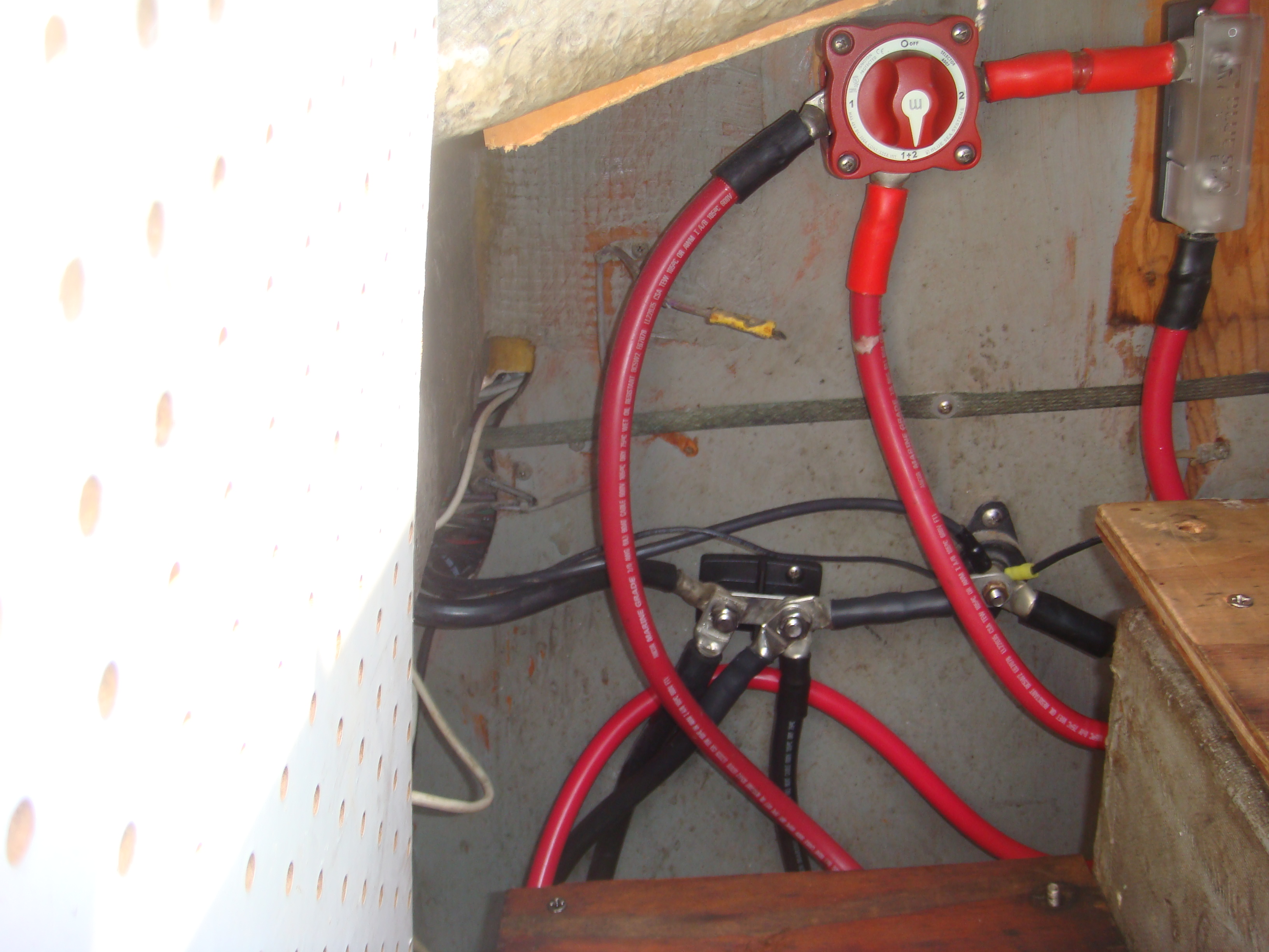 Dual Terminal Post For Negative Battery Cables |
| Running the Power Cables | |
|
Once I had decided to run 1/0 electrical cables from the
house battery bank to the bow I found it very easy to keep
putting off that job. Only boat mainenance job I hate more
than electrical wiring is plumbing.
|
|
| After looking at a number of potential solutions to these issues, I decided to route the pigtails through the base of the on deck anchor well using Blue Sea Cable Clams. I will use a dual power post mounted on the underside of the anchor well to connect the cables. | |
|
I had initially dismissed the Cable Clams for the power cables
as I thought they could not accommodate the outside diameter of
the 1/0 cable. Having not come up with any other workable
solution in several weeks, I checked the specs on the largest of
the Cable Clams (pic on the right). The specs say the
largest cable diameter it can handle is 0.56" (14mm). I
measured the diameter of my cable and it was 0.56"! I normally don't like to max out the specs on any product, but in this case the Cable Clam will be used for the windlass pigtails, which are 50 mm2. The outside diameter of this cable is about 0.38", easily within the specs of the Cable Clam. In the past I've had difficulty drilling the hole in the rubber seal for the cable. A standard twist drill bit does not remove enough material to allow the seal fit around the cable and also fit inside the compress collar. For power cables this could be a big problem. Then I thought of using a Forstner bit. That worked great as I could drill a hole just smaller that the O.D. of the cable and still have it fit in the collar and not leak. |
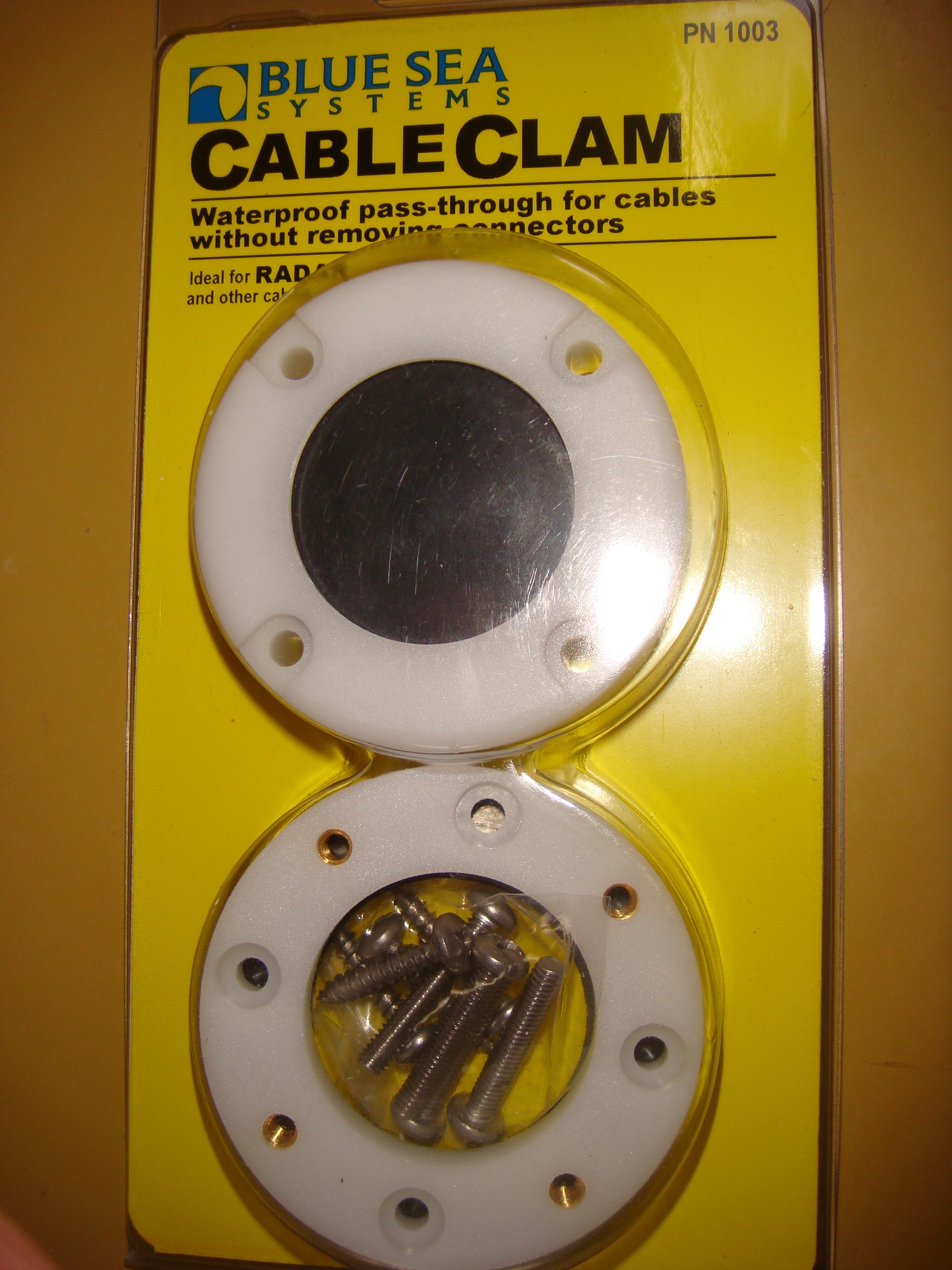 Largest Blue Sea Cable Clam |
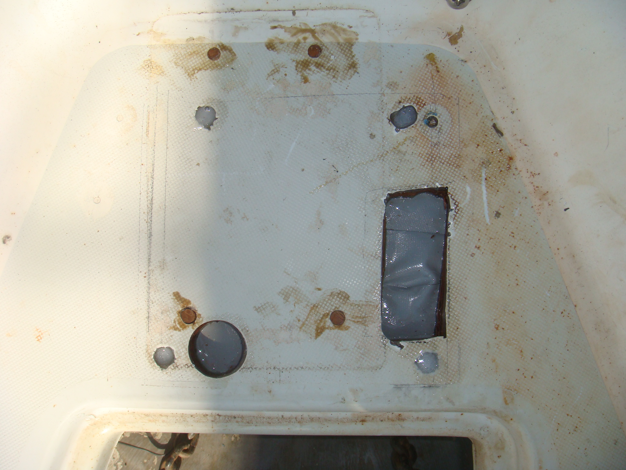
 Underside of the On Deck Anchor Locker |
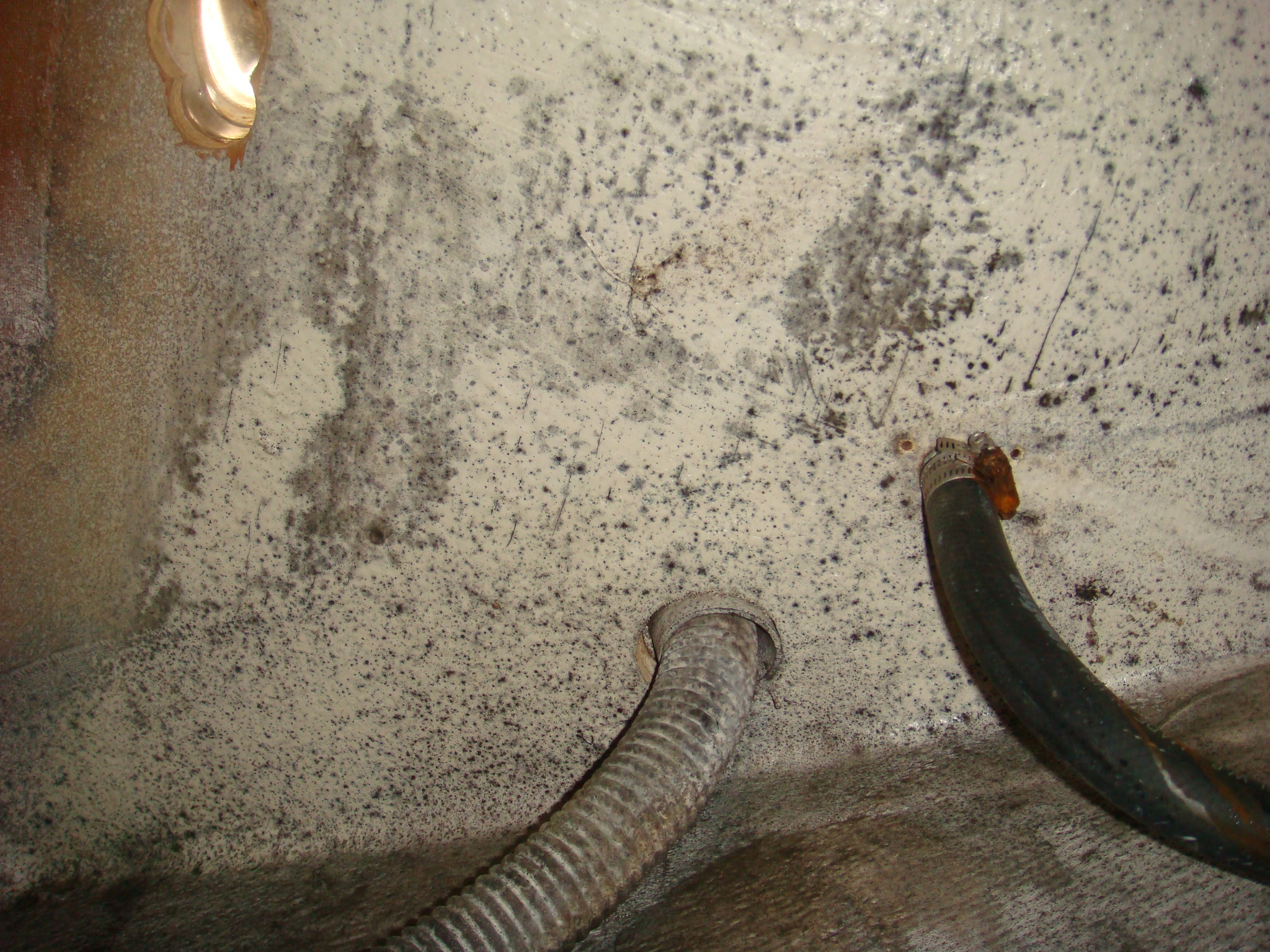
Having decided to use the Cable Clams to route the power cables
through the floor of the anchor locker into the chain locker
below, I needed to move all of the anchor rode out of the chain
locker. The picture on the left shows the underside of the anchor locker from inside the chain locker. The existing hoses in this location are the fill hose (white) for the bow water tank, and the hose (black) for the anchor washdown. |
| At this time I also noticed a problem with the hose for the washdown - it has been lying on the bottom of the chain locker with 300' of 5/16" chain lying on top of it. Fortunately that is wire re-enforced water hose so it did not collapse or break under the load of the anchor rode. However, this is a good time to re-route the hose so that the anchor rode does not ride on top of it. |
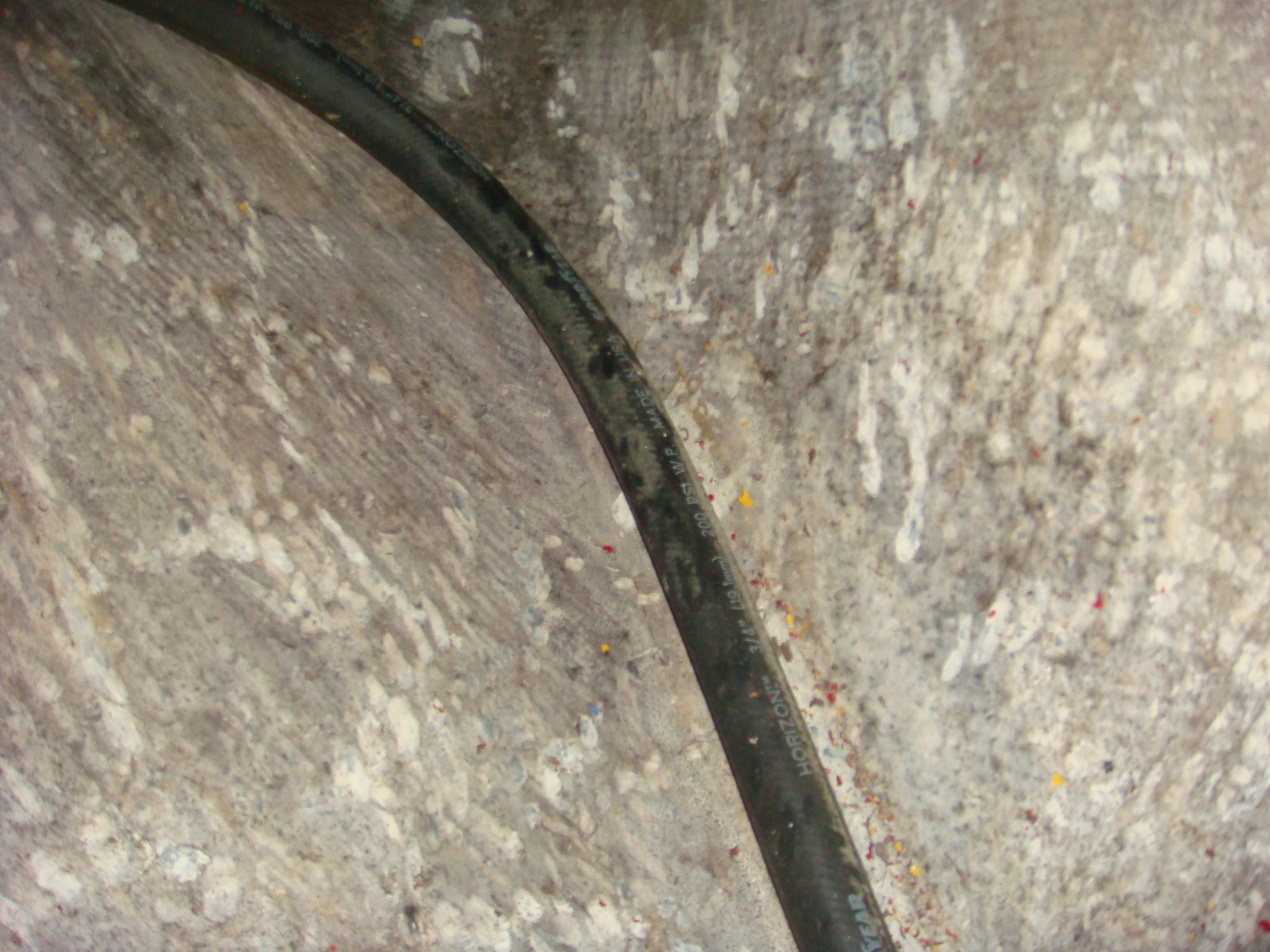 Washdown Hose Laying on the Bottom of the Chain Locker |
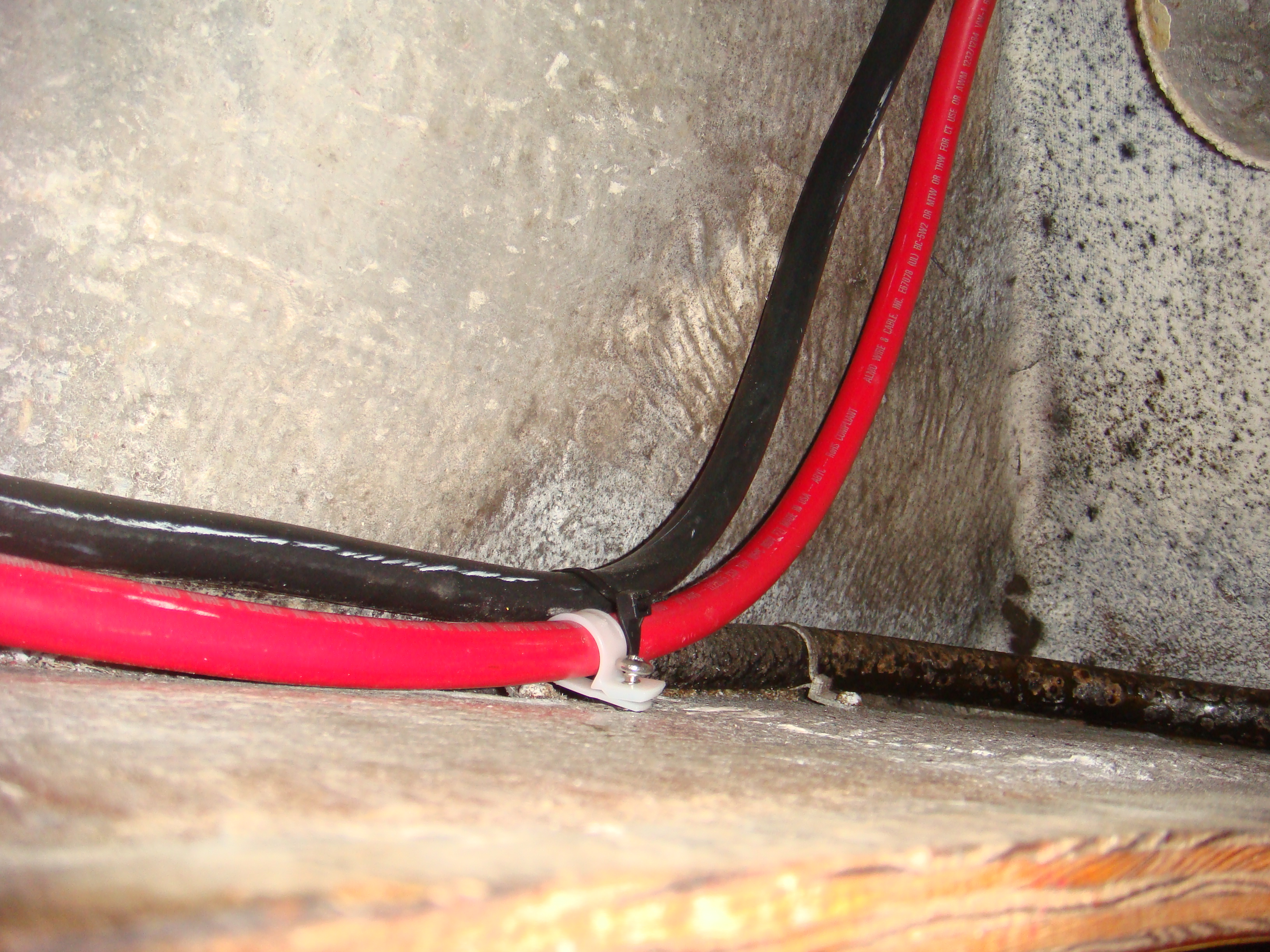
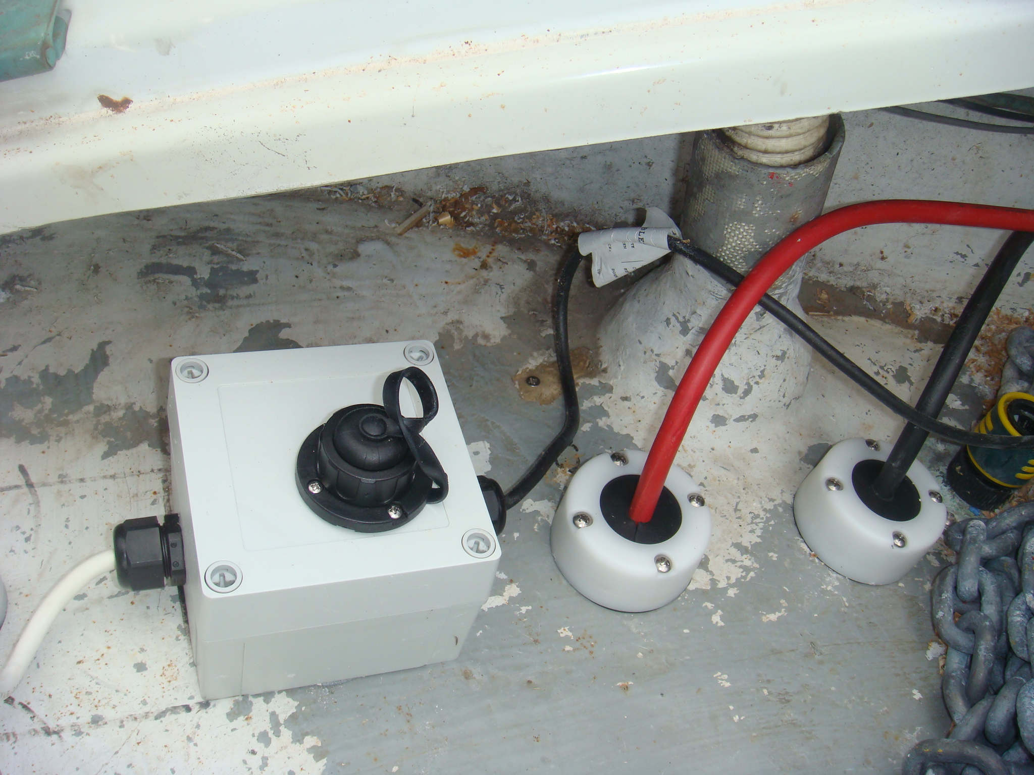 Power Cables Sealed By Cable Clams |
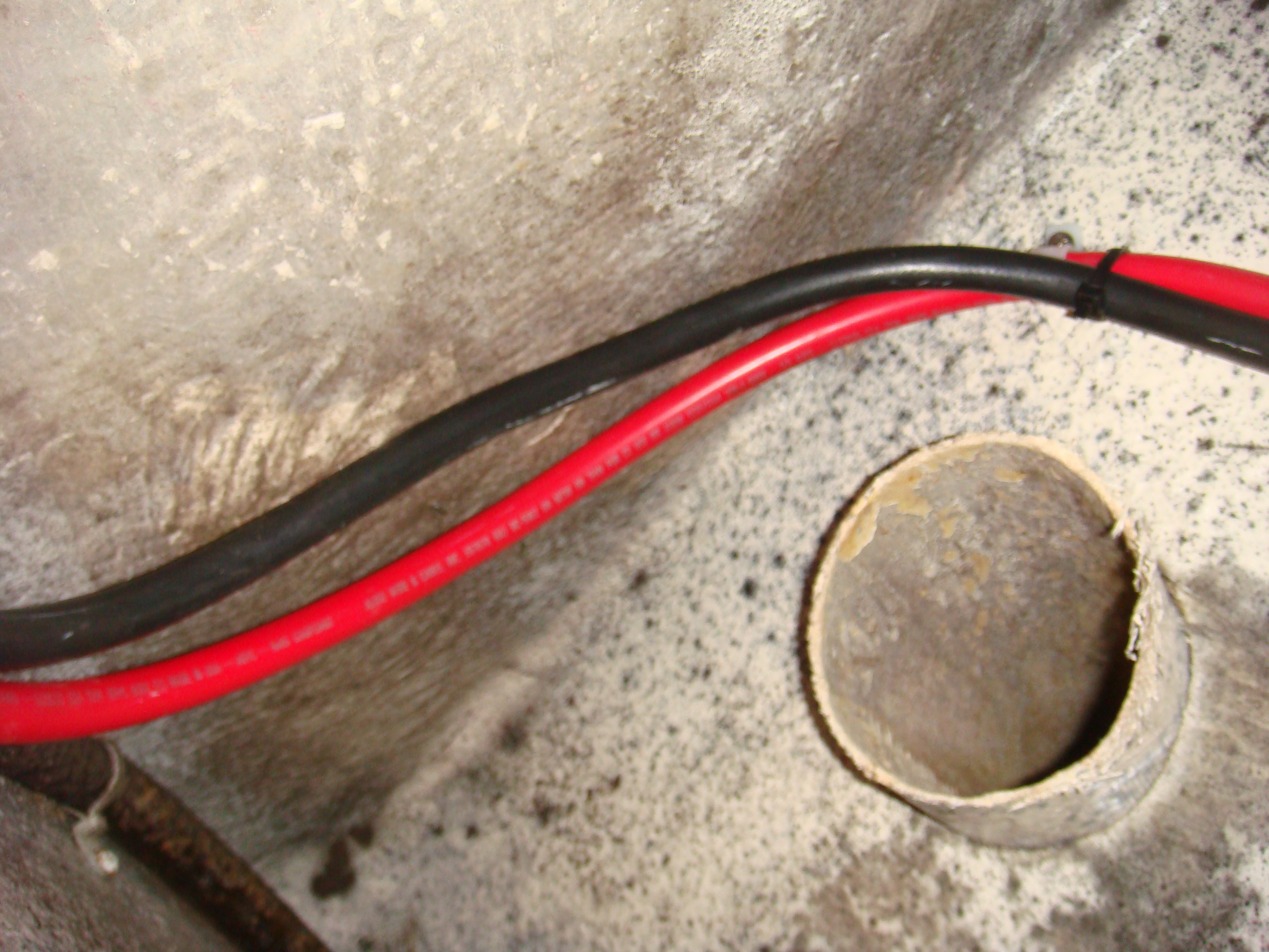
Before running the 1/0 cables from the cockpit to the chain
locker, I drilled holes in the floor of the anchor locker for
the pigtail power cables from the windlass. I sealed the holes and the cables with the Blue Sea Cable Clams described above. I still have to secure the cables to the underside of the deck, but that will wait until I have all of power cables run and the windlass operational. |
| I have mounted a Blue Sea dual post terminal to the under side of the deck chain locker. In the picture on the right the pigtails from the windlass have been secured to the posts from the right side. The power cables from the cockpit locker come from the left. |
 Dual Post Terminal in Chain Locker |
 Cables Secured to the Top of the Chain Locker |
From the cable post the power cables are routed along the under side of the deck chain locker to the starboard side of the below decks locker. |
| Then down the bulkhead between the chain locker and the forward cabin. |
 Cables Secured to the Chain Locker Bulkhead |
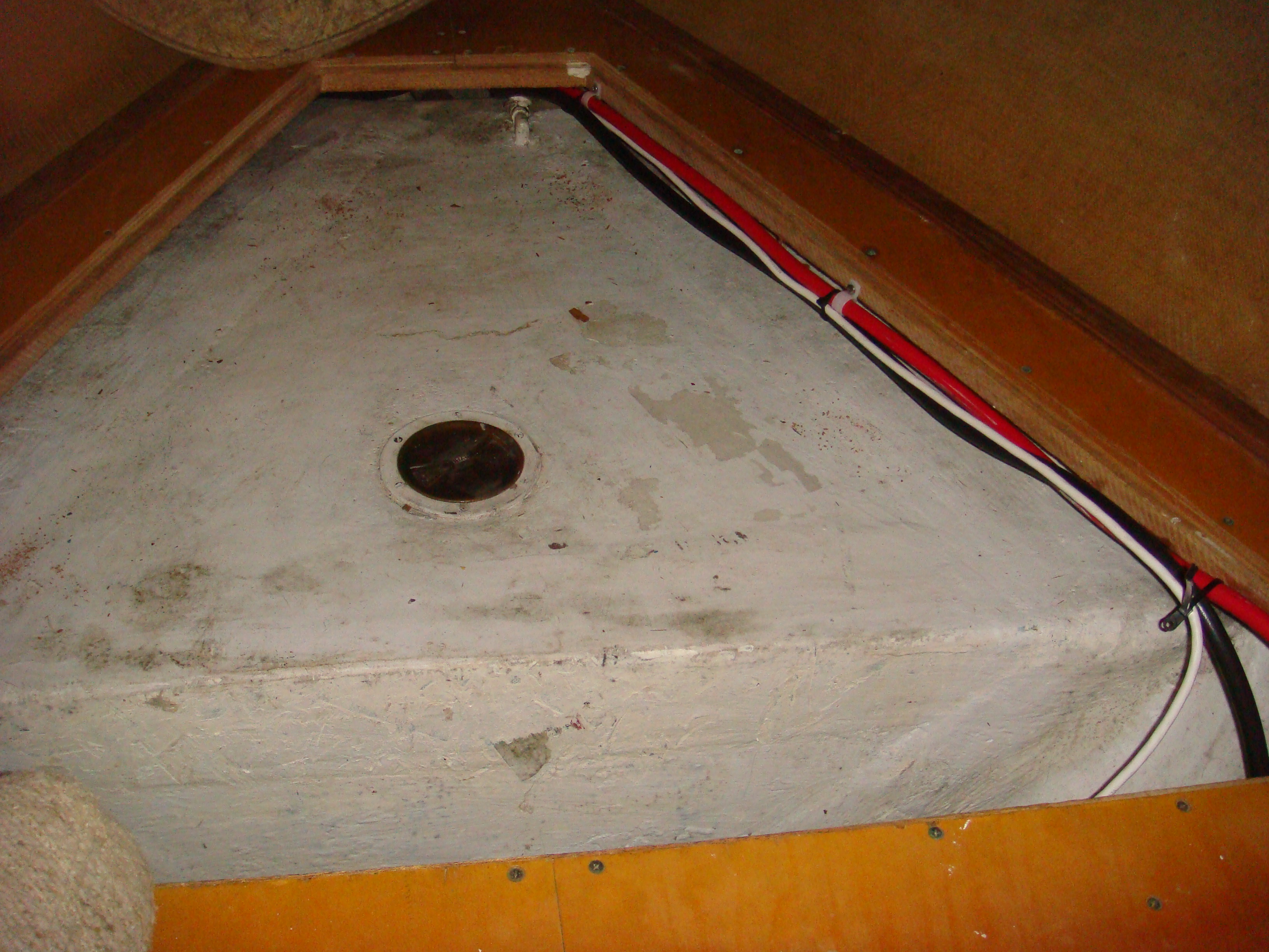 Water Tank Under the V-Berth |
The cables are routed over the starboard side of the bow water tank under the V-Berth. |
| From the V-Berth the cables are routed under the cabin sole to the starboard cockpit locker. In the picture on the right, the cables are secured to one of cleats for the starboard hatch in the main saloon. |
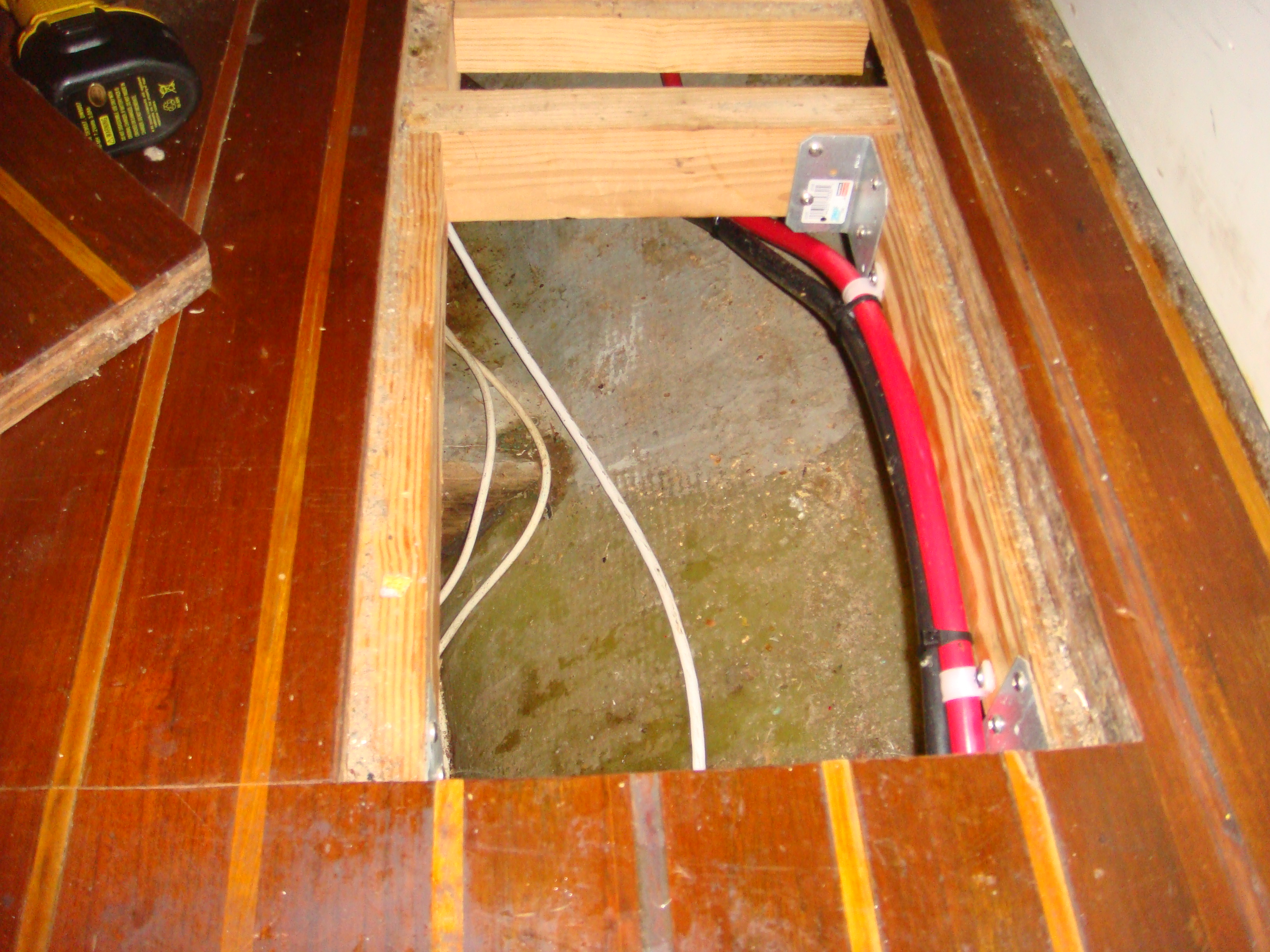 Starboard Cabin Sole Hatch in Main Saloon |
| Remote Controls and Chain Counter | |
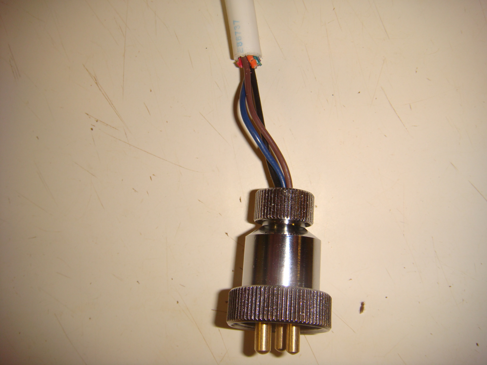
| Along with the windlass I also purchased the remote chain
counter offered by Quick (CHC 1102 M). This comes with a
deck receptacle for the remote control. The chain counter and
one receptacle are shown in the picture on the right. I also purchased a second deck receptacle to allow me to operate the windlass via the remote control from either the cockpit or the foredeck. There are times when I will need to operate the windlass from either location. |
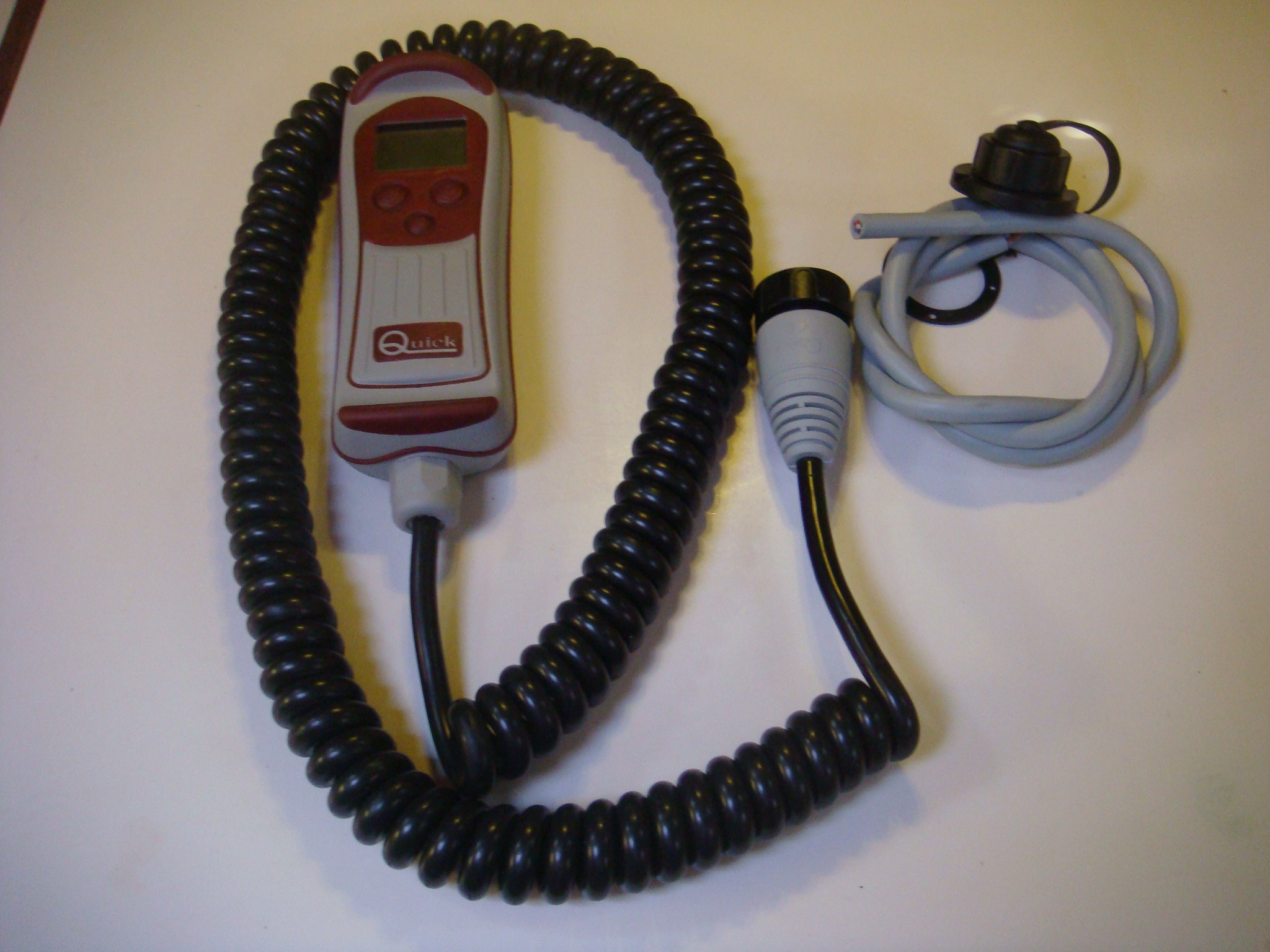 Remote Chain Counter and Deck Recptacle |
| Many windlass installations use foot switches on the foredeck to operate the windlass. My experience on a few boats with foot switches motivated me to not go that way. On several occasions when on the foredeck operating the windlass with the foot switches, the rocking of the boat caused me to shuffle my feet to keep my balance and I stepped on one or both of the switches. This resulted in the anchor chain going out or in, when I wanted it to do the opposite or do neither. In more than one instance my stepping on the wrong switch tripped the main breaker for windlass. I probably should admit that all my life I have been clumsy (especially when it comes to putting my foot on the spot I intended). Others may not have my problem with foot switches. However this installation must take into account my short comings - hence, no foot switches on the foredeck. | |
| On the right is a wiring diagram (double click to view at full resolution) for the two remote chain counter receptacles. Power will be provided off the main electrical panel with a dedicated 5A circuit breaker. The receptacles come with a 3' pigtail wire containing 7 conductors. The pigtails for each receptacle will be terminated onto a terminal strip enclosed in a water-tight junction box. |
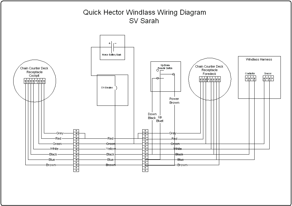 Wiring Diagram for Remote Chain Counter |
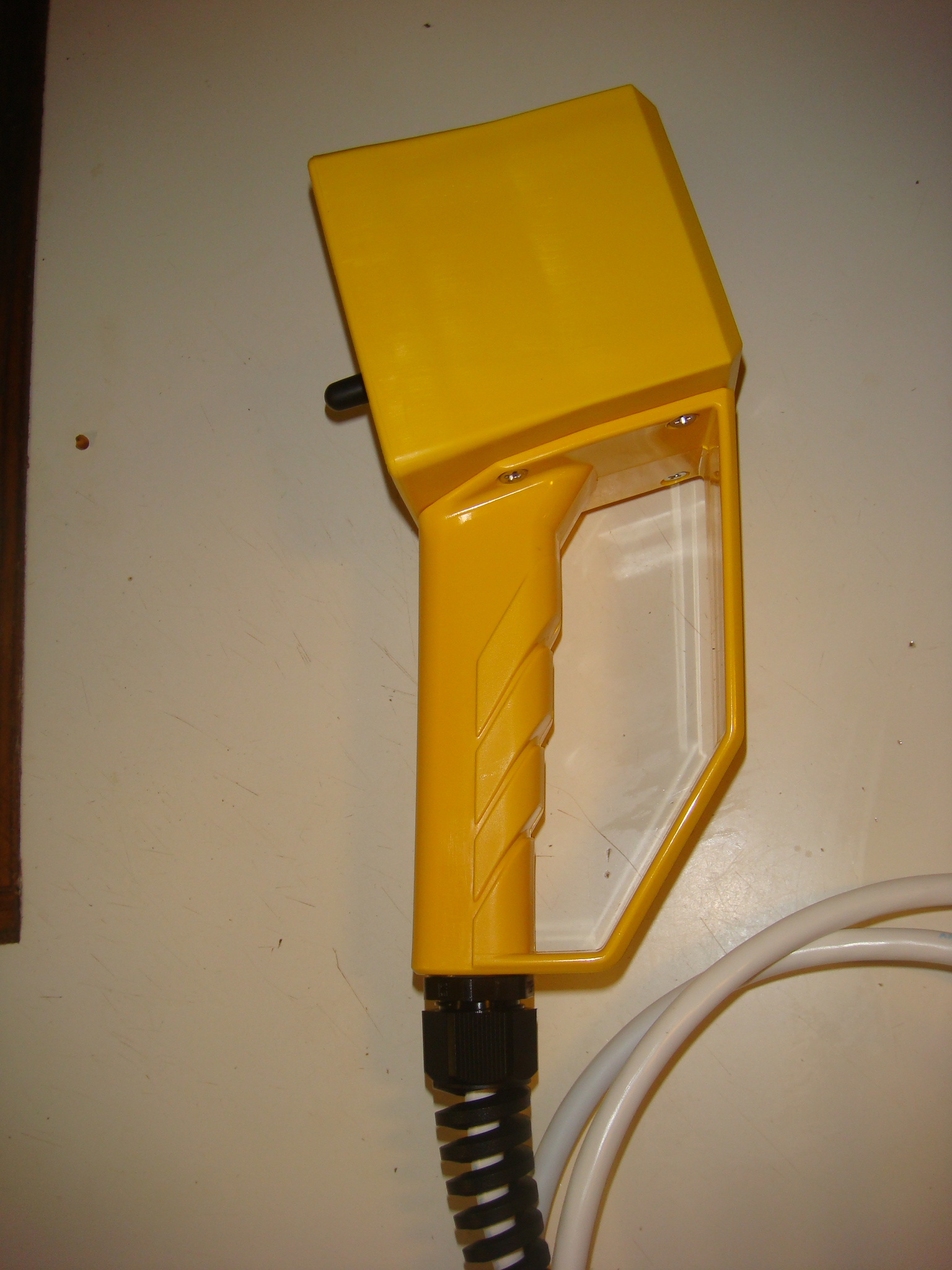
 Junction Box for the Remote Control Cable |
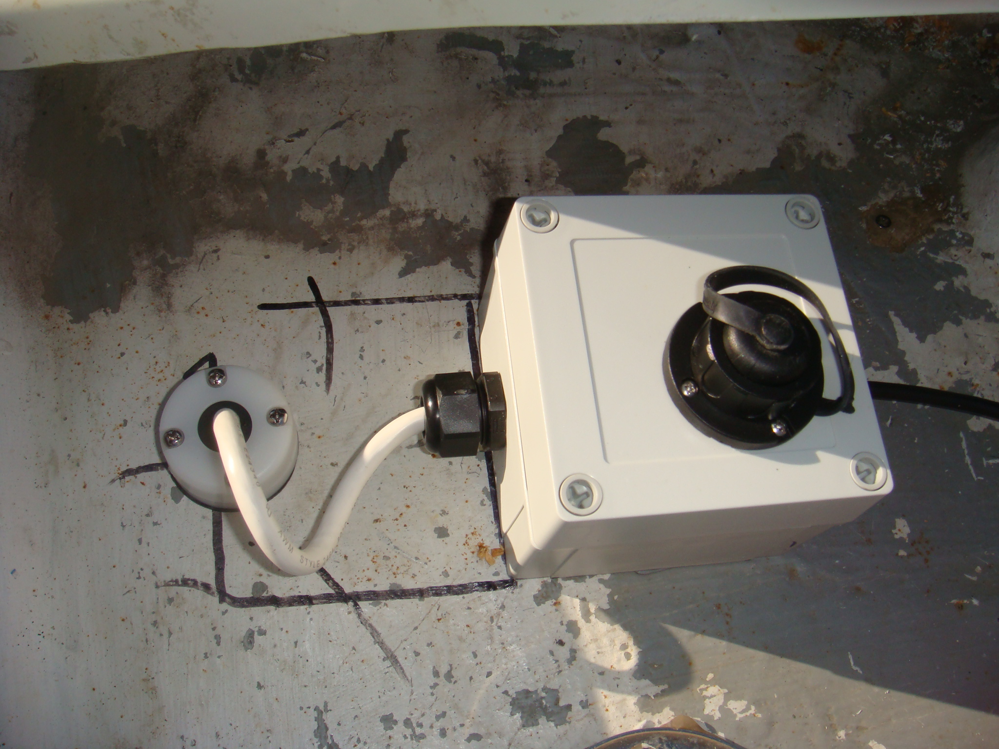
On the left is a FIBOX enclosure I purchased through
McMaster-Carr. These are pricey boxes compared to the
enclosures offered by Lowe's and Home Depot, but they are much
more robust. I have mounted one of the receptacles for the Remote Chain Counter on the lid of this enclosure. The enclosure has been mounted in the aft portion of the on deck anchor well. The black cable on the right side of the picture is the control cable from the windlass. The white cable on the left side of the picture is main cable that runs from the chain locker to a terminal strip in the aft hanging locker. That cable passes through the floor of the anchor well using a Blue Sea Cable Clam. Both cables are secured to the enclosure by clamping liquid cable seals. The anchor locker can be wet and this enclosure needs to be water tight. |
| The picture on the right shows the inside of the junction
box. I have mounted a terminal strip in the base of enclosure. Notice the gasket seal on the rim of the enclosure and that the closure screws are plastic. They are also contained within the lid and are unlikely to ever be dropped overboard. I still have to mount a 3-wire receptacle on the lid of the enclosure for the Up/Down switch, which is a backup to the remote chain counter. |
 Inside the Junction Box |
| The wiring diagram documents how the conductors on the pigtails and the main cable will be connected. The wire colors in the main cable do not completely match those in the pigtails. | |
 Remote Chain Counter Receptacle in Cockpit |
For cockpit remote control I have mounted the 2nd receptacle in the side of the cockpit well, near the bridge deck. |
| When the windlass is in use I will likely keep the remote chain counter in the cockpit mounted on the bridge deck. When I need to operate the windlass from the foredeck I will likely use the Up/Down Switch. |
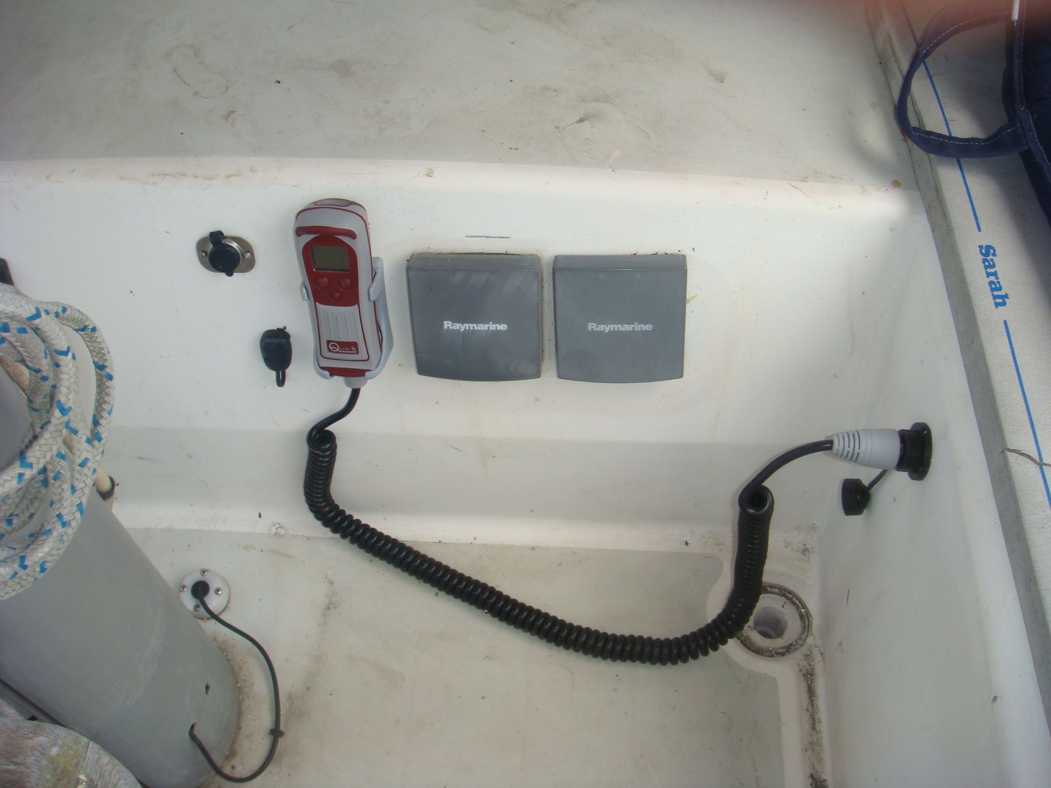 Remote Chain Counter in the Cockpit |
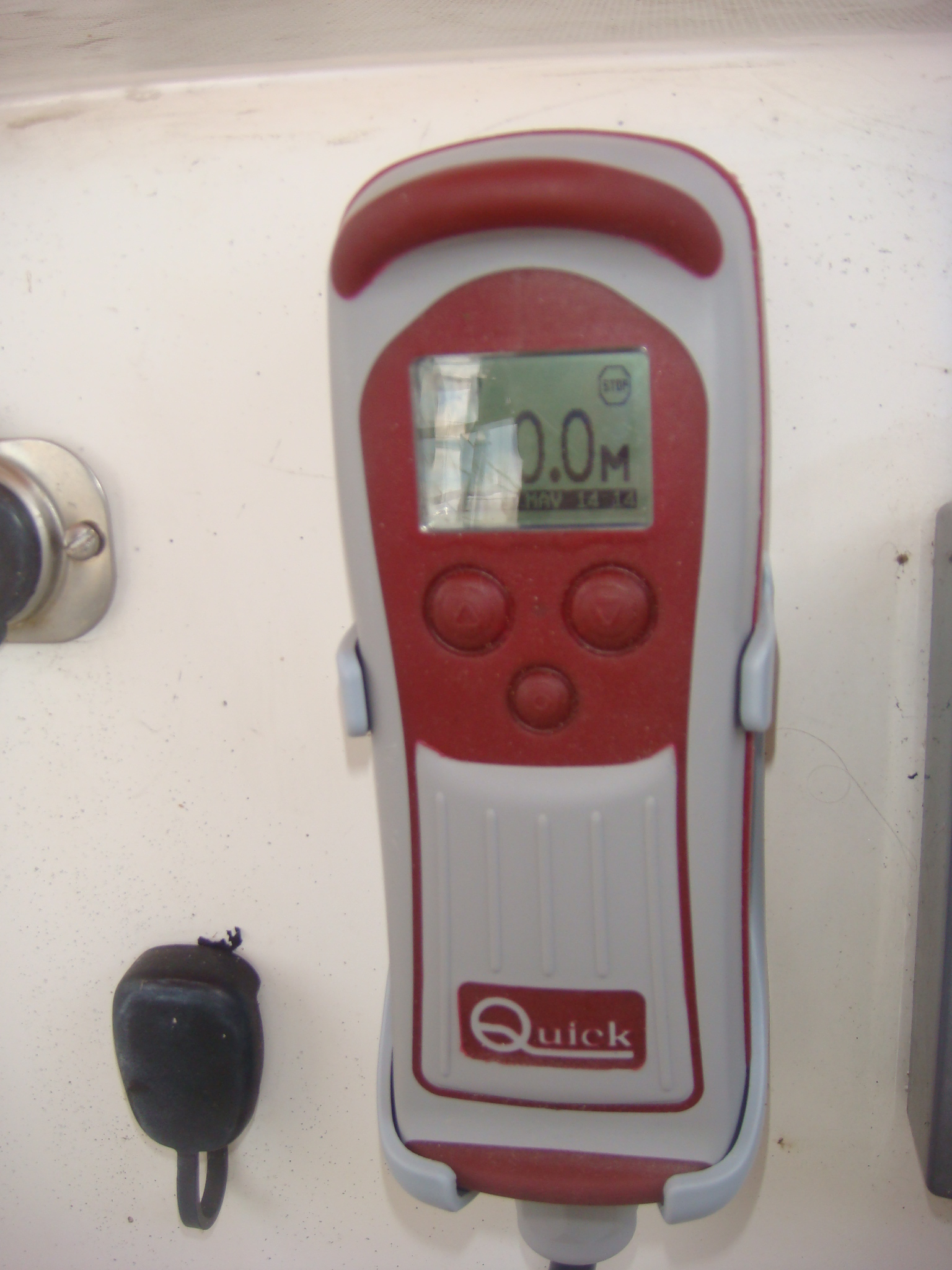 Remote Chain Counter Controller |
On the left is the Remote Chain Counter controller in the bracket on the bridge deck of the cockpit. |
| On the right is a closeup of the LCD display on the controller. |
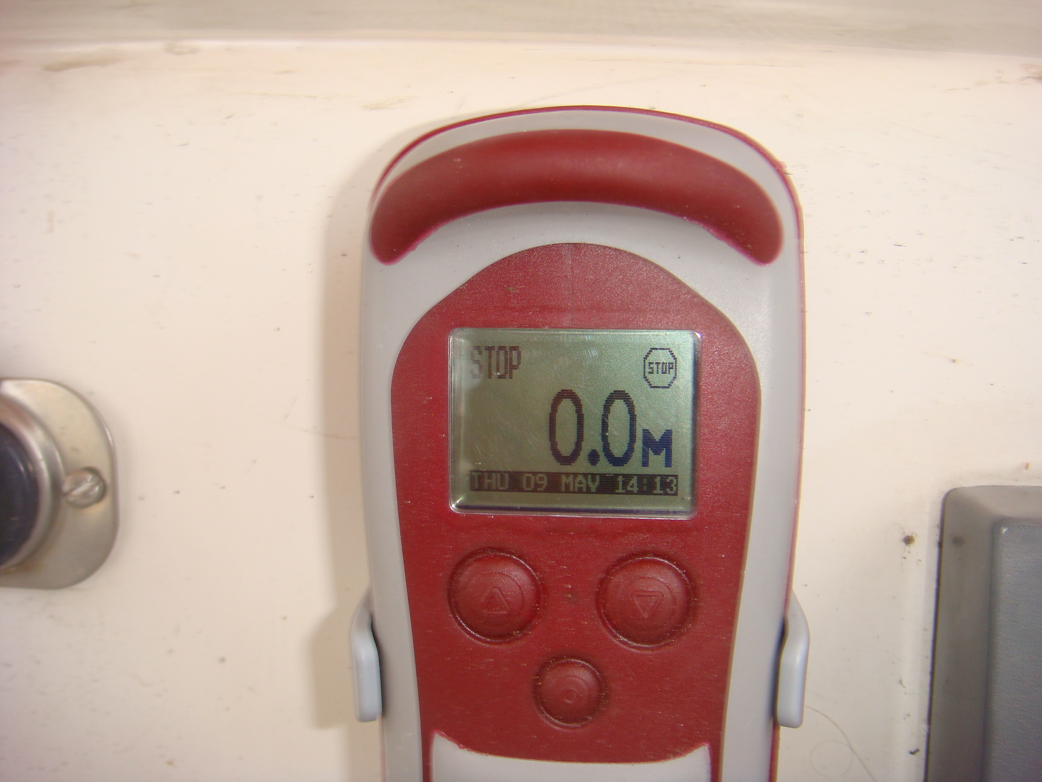 Controller Display |
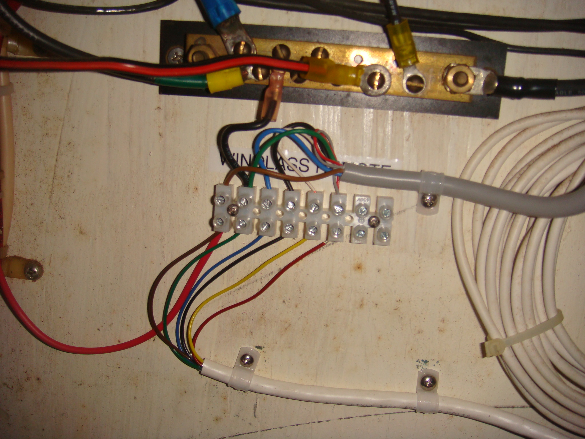 Terminal Strip in Aft Cabin Hanging Locker |
The deck receptacle in the cockpit is connected to a terminal strip on the electrical distribution panel in the aft cabin hanging locker. The cable from the cockpit receptacle is connected at the top of the terminal strip. The cable from the receptacle in the anchor locker is connected to the bottom of the strip. |
| The remote cabling gets its power from a 5A breaker (4th from the top) on the auxiliary electrical panel above the navigation station. |
 5 Amp Breaker for Windlass Remote |
| Up/Down Switch | |
| The schematic above shows an up/down switch (SPDTCO) in addition to the
deck receptacles for the chain counter. This switch has
been
installed in another enclosure from McMaster-Carr - in this case
a hand-held enclosure. I will install a 3-wire receptacle
in the lid of the enclosure box shown above. The UP/Down
switch will connect to this receptacle using more 8 conductor
wire, but I will only use the Black, Blue and Brown conductors
in this wire. The only 3 conductor wire I could find was
16 AWG for a bilge pump switch, and none of the local stores had
it in stock. |
 Up/Down Remote Control |
 Up/Down Remote Control, Side View |
This setup will give me two hand-held windlass controls.
The remote chain counter can be used in the cockpit or on the
foredeck. The UP/Down control can be used only on the
foredeck. In addition to being a backup to the remote chain counter, this switch will be used to operate the rope drum on the windlass. The rope drum will be used for my back up anchor (Fortress) and for when the windlass is used as a deck winch. In both cases the chain count function is of no value. |
| I purchased a pair of Hella water-tight, 3-wire deck receptacles a plugs. The plug, shown on the right, is too small for the O.D. of the 8-conductor cable. So I had strip off a couple of inches of the insulation cover and remove the 5 unused wires in order to hook up the plug. This left the 3-wires in use (brown, black & blue) outside the covering insulation and probably compromised the water-tightness of the plug. |
 Hella 3-Wire Plug |
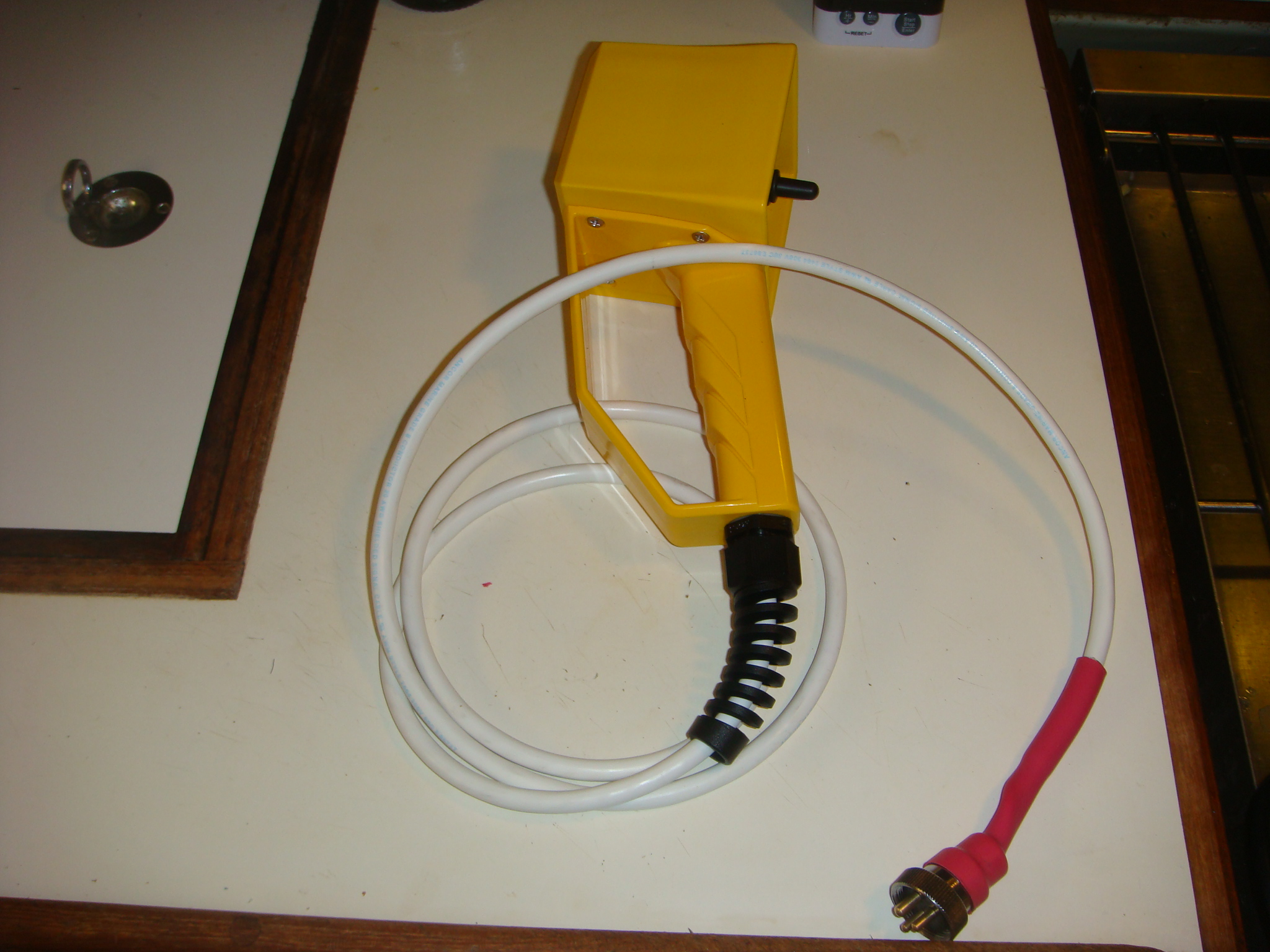 Plug Sealed with Shrink Tubing |
I used a long piece of 3/4" shrink tubing to provide a cover for the exposed wires and to povide a water-tight seal on the plug. |
| On the right is a pin-out of the plug as seen from the cable end (looking down toward the deck receptacle). The large pin at the bottom is connected to the brown wire for power. The smaller pins at the top are connected to the blue wire (upper left) for the up function and the black wire (upper right) for the down function. |
 Pin-Out of Plug for Up/Down Switch |
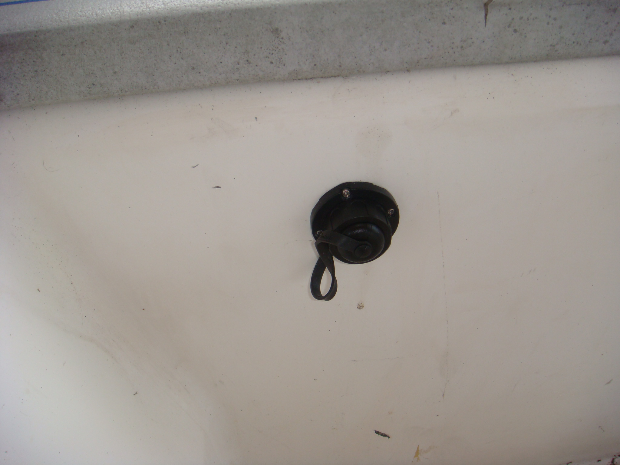
 Receiptacle for the Up/Down Switch Installed on the Junction Box in the Anchor Locker |
For now I've installed a receiptacle for the Up/Down switch only
in the junction box in anchor locker on the fore deck. I
plan to use the Remote Chain Counter primarily in cockpit.
I will use the Up/Down switch when I need to operate the
windlass from the deck. With the Remote Chain Counter powered on in the cockpit it will provide the chain count even when the windlass is operated by the Up/Down switch. Note that the retaining strap for the cap on the chain counter receptacle has already broken. There's more than a good chance I'll drop this cap in the drink in the future. Need to purchase a spare cap (or two). |
| Modifying the Anchor Locker Hatch | |
| As stated in the planning section at the top of this page, I knew I would have to modify the hatch over the anchor locker because the aft end of the windlass overhangs the openning for this locker. | |
| The simple solution for this issue was
to cut off the forward section of the hatch, leaving the hinges
on the aft section. Now the forward section can be
permanently screwed into the deck and the aft portion can swing
clear of the windlass providing access to the anchor locker. I took the hatch to Jeff Wilder who cut the Ipe block on which the windlass is mounted and had him cut off the forward section of the hatch using his radial arm saw. In the picture on the right I have placed both sections of the hatch over the locker openning. |
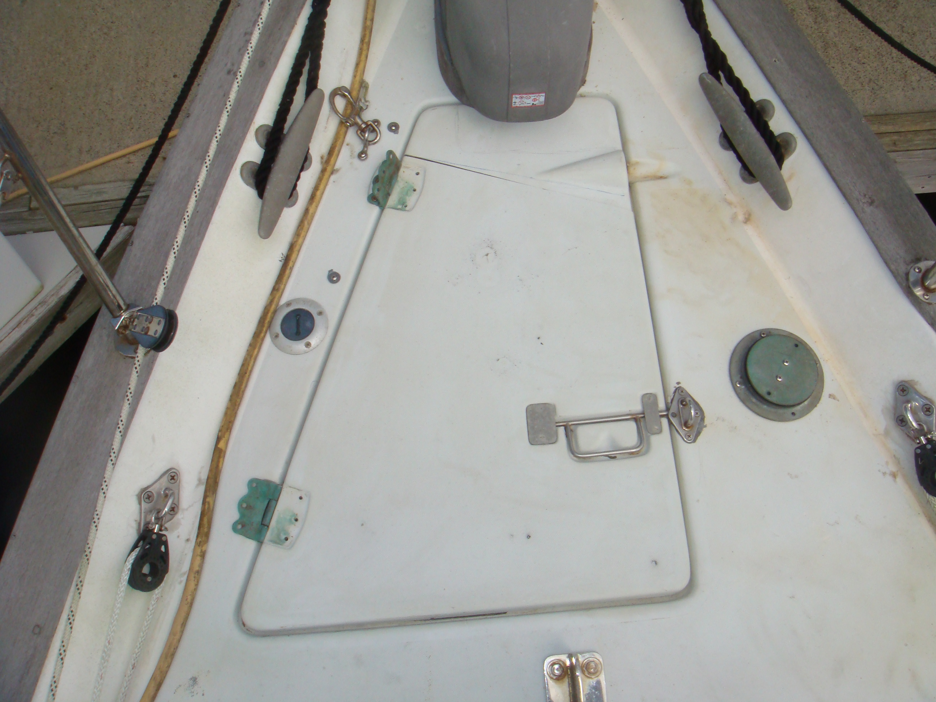 Cut Sections of the Hatch Set In Place |
 The Forward Section of the Hatch, Which Will Be Secured in Place |
I only have hand cutting tools, and I was concerned that I
would not have enough control of the saw to make a clean
straight cut. Jeff made the cut in about 10 seconds. In the picture on the left I have removed the aft section of the hatch after verifying it will swing clear of the windlass. |
| I was a little surprised that the hatch
is balsa-cored. Well, Sarah is hull #2 and I suspect
Pearson went with plywood on later hulls. I will have to seal the cut edges with epoxy. |
 The Hatch is Balsa-Cored |
 Remote Up/Down Switch Mounted on Anchor Locker Hatch |
The last task after remounting the anchor locker hatch was to
secure the holder for the remote up/down switch on the underside
of the hatch. This provides a place leave the switch on
the foredeck while at anchor. If I need take up or let out
chain the switch will be ready for use. Although the
switch is water-tight, I can close the hatch with switch in
place if it starts to rain. When underway I will take the switch back to the cockpit. |
| I still have a few cleanup task to finish, but essentially the windlass installation is complete as of Oct 9, 2013. I will only update this page if I modify the installation. | |
| After One Winter Anchored in the Bahamas | |
| In late January, 2014 Steve Angst joined me to
sail Sarah to the Bahamas. We had cold, nasty weather for the
first part of the trip and went down the AICW to St. Lucie
before heading across the Florida Strait to the Abacos. Then I
spent two months mostly at anchor in the Abacos before returning
to Jacksonville in late April. This cruise exposed a number of problems with my installation. |
|
|
|
| On Retaining the On Deck Anchor Locker | |
| When I started the windlass installation
project I had the option of removing and glassing over the on
deck anchor locker. I had previously
modified this locker to allow me to stage the chain rode in
the locker with my manual Lofrans windlass. Because the
Quick windlass requires a chain slot in the deck rather than
just a pipe, making a water tight chain passage that went from
the foredeck through this locker was not something I wanted to
attempt. I elected (for now) to retain the locker and make it part of the new installation. I could see a lot of advantages to removing that locker and creating one large locker below decks in which the chain could easily fall. However that would be a lot of work and I would likely need to hire someone with more expertise than I to do the glass work. Now that I've spent one winter using the windlass I can see the PROs and CONs of retaining this locker. |
|
PROs:
|
|
CONs:
|
|
| I'm still undecided if I will retain the on deck locker. The emergency CON is my primary concern. One thought to mitigate that concern would be to insert a short (< 1') length of 5/8" rope in the chain every 100' feet or so using crown splices. That would allow me to easily cut and release the chain in use without having to pull all of the chain on deck. The rope should also pass through the windlass. | |