Sailing Vessel (SV) Sarah
Sarah has a new owner as of 7/26/2021. There will be no more updates to these SV Sarah pages
Sarah has a new owner as of 7/26/2021. There will be no more updates to these SV Sarah pages
| 12VDC Electric Upgrades | |
| Although the major changes to the electrical systems on Sarah are on the AC side to accommodate European power, I still have a number of upgrades to accomplish on the 12VDC systems. The significant changes are listed on the right | |
| Distribution Panel | |
|
Almost all of the electrcial circuits controlled from the breaker panel
above the navigation station are distributed from the set of terminal strips
shown on the right. This distrbution panel is located in the back of
the hanging locker in the aft cabin is covered by a piece peg board. Most of this wiring is original from the Pearson factory or by a Previous Owner (PO). When I purchased the boat there was no documentation on these circuits. Someone tried to document them by writing on the bulkhead above and below the terminal strips. Most of that documentation has faded with the years or is obstructed by the wiring Everytime I've had to make a modification to wiring on Sarah I've had to test these circuits to find out what they do and where they go. When I've made that determination I document that circuit in the wiring diagram below. |
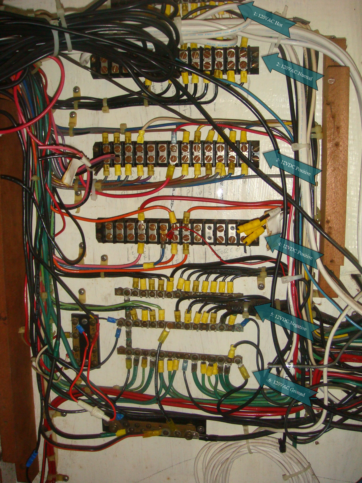 Electrical Distribution Panel in Aft Cabin Hanging Locker |
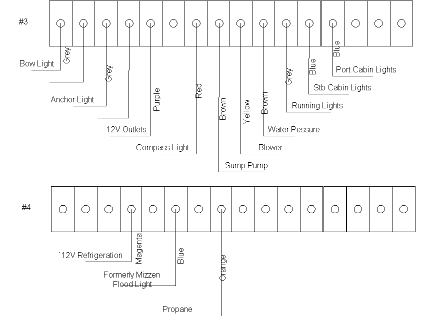 Rows 3 and 4 of Terminal Strips |
The diagram on the left covers the 3rd and 4th row of terminal strips on the panel. In the picture above these are the strips in what appears to be the 2nd and 3rd row. There is a terminal strip at the top of the picture, obscured by the wiring. |
| Battery Switch | |
The battery switch I inherited on Sarah was the conventional single
rotary switch (Battery 2, Both, Battery 1, Off), with all circuits wired to
the output terminal on the switch. This wiring presented the following
limitations/problems:
My solution for these issues is to:
Under normal operation there should be no reason to change the switch settings. Should one of the batteries fail to hold charge it can be switched off, and the remaining battery can supply all functions. |
|
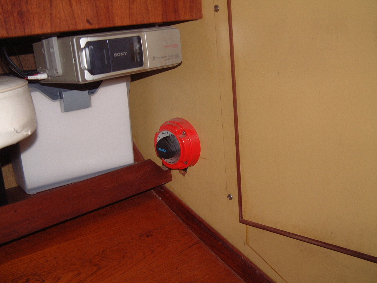 Here is the original battery selector switch.
A
quality item, but the way it is wired presents all of the issues described
above. Here is the original battery selector switch.
A
quality item, but the way it is wired presents all of the issues described
above. |
|
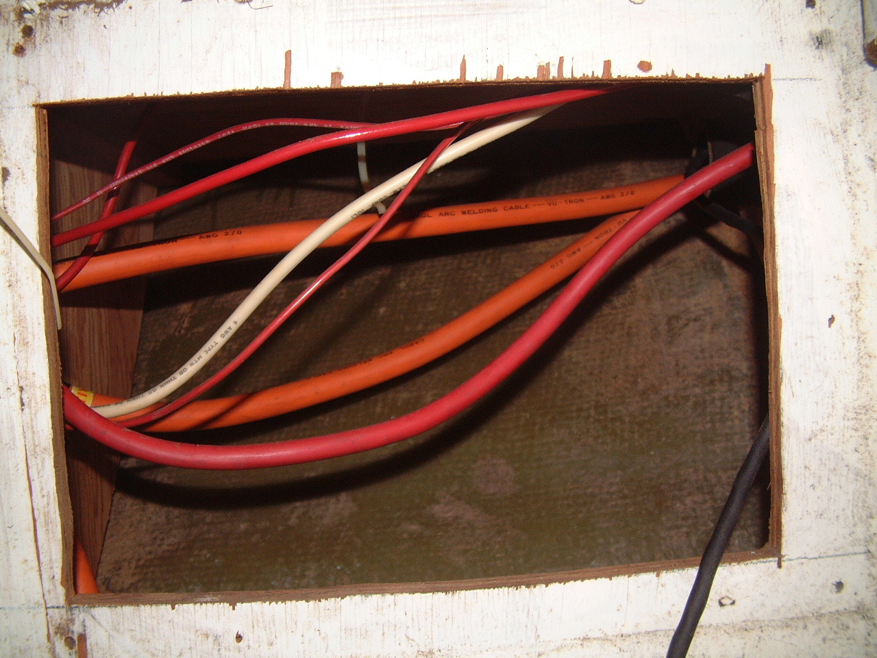 Here is the cable area behind the switch, viewed from in the hanging
locker. Here is the cable area behind the switch, viewed from in the hanging
locker.
|
|
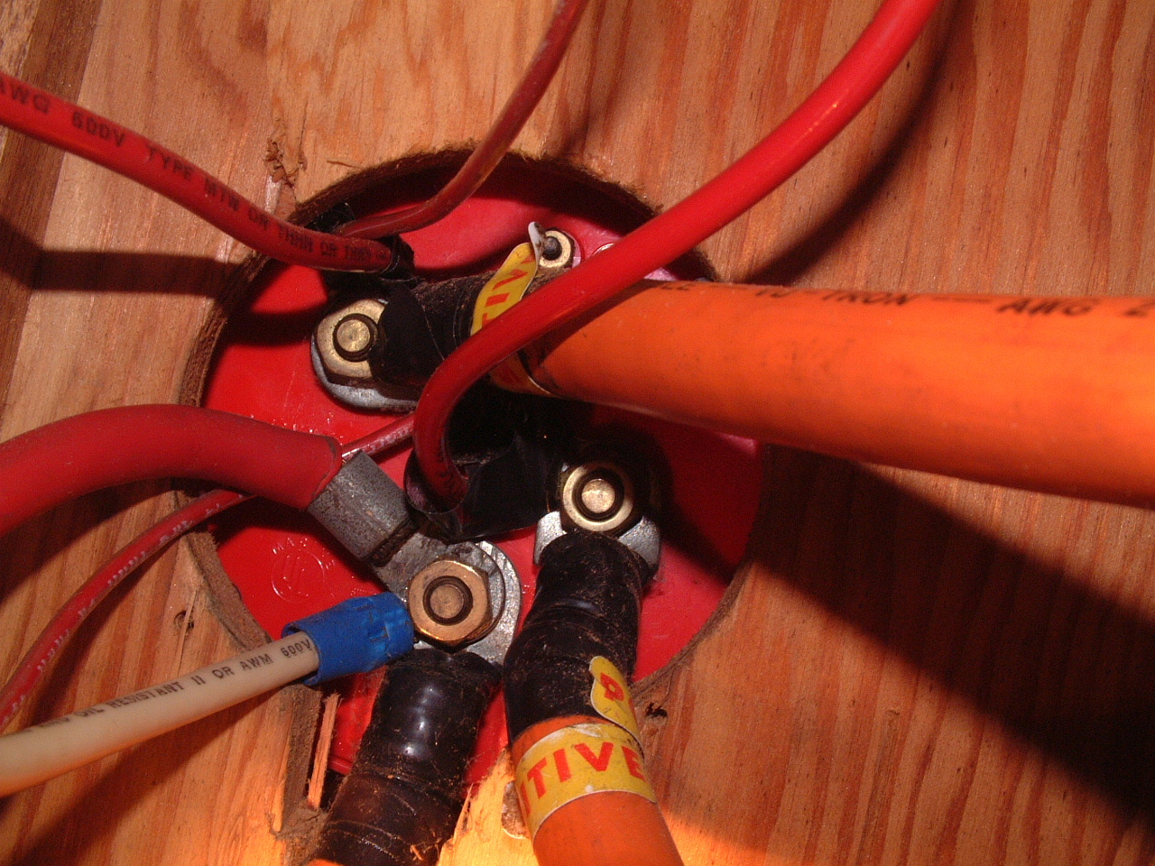 As usual the major problem was removing the old equipment rather than
installing the new.
I
don't know how someone connected these wires to the old switch, but it took me
the better part of a morning to get them off. The stiffness and length
of the cables prevented me from pulling the switch away from the bulkhead to
get at the connections. The cable congestion
prevented me from putting a socket on the nuts. So I had to remove the nuts
with a set of needle-nose pliers, turning the nut 1/16 revolution at a
time. The picture was taken by holding the camera in the cable area and
turning it 90 degrees. I could barely see the back of the switch, and not
at all when my hands were in the cable area. Basically I had to take
the nuts off the posts by feel. As usual the major problem was removing the old equipment rather than
installing the new.
I
don't know how someone connected these wires to the old switch, but it took me
the better part of a morning to get them off. The stiffness and length
of the cables prevented me from pulling the switch away from the bulkhead to
get at the connections. The cable congestion
prevented me from putting a socket on the nuts. So I had to remove the nuts
with a set of needle-nose pliers, turning the nut 1/16 revolution at a
time. The picture was taken by holding the camera in the cable area and
turning it 90 degrees. I could barely see the back of the switch, and not
at all when my hands were in the cable area. Basically I had to take
the nuts off the posts by feel. |
|
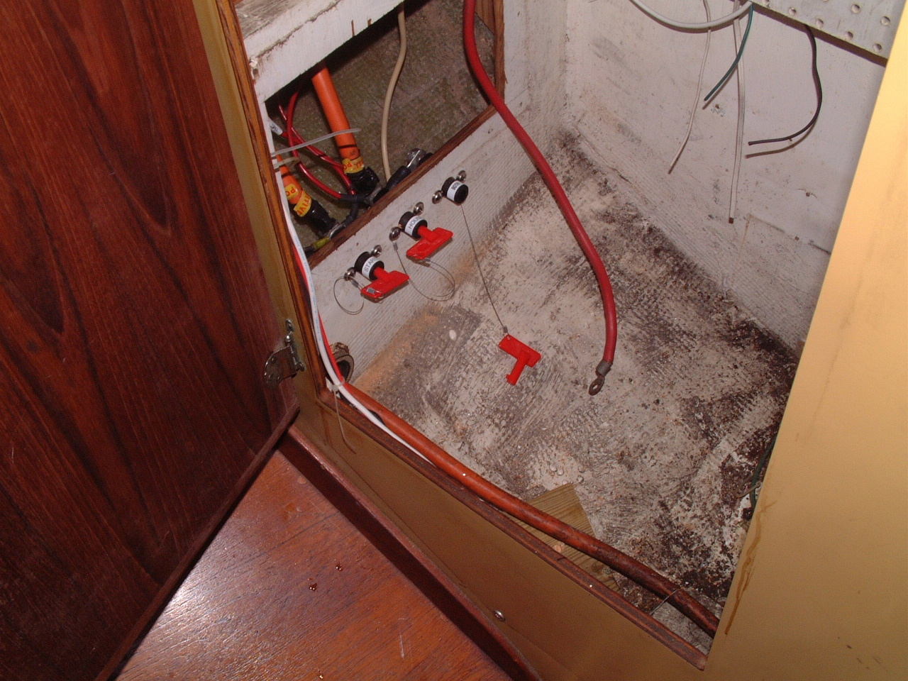 Here are the new switches installed inside the
hanaging locker.
Only
when I had drilled the holes and fitted the switches did I discover that I
could have put the switches in a better orientation. If they had been
rotated 90 degrees that would have put the switch keys in the vertical
position when "ON" or closed. That orientation would have precluded any
loose item in the locker from falling on the handle and turning the switch
to the "OFF" position. The keys can be removed when the switch is in the "OFF"
position. I believe it still would be difficult for anything in the locker
to move the switch, so for now they will stay as fitted. Of course it is
possible, so it is almost 100% that it will happen sometime. Here are the new switches installed inside the
hanaging locker.
Only
when I had drilled the holes and fitted the switches did I discover that I
could have put the switches in a better orientation. If they had been
rotated 90 degrees that would have put the switch keys in the vertical
position when "ON" or closed. That orientation would have precluded any
loose item in the locker from falling on the handle and turning the switch
to the "OFF" position. The keys can be removed when the switch is in the "OFF"
position. I believe it still would be difficult for anything in the locker
to move the switch, so for now they will stay as fitted. Of course it is
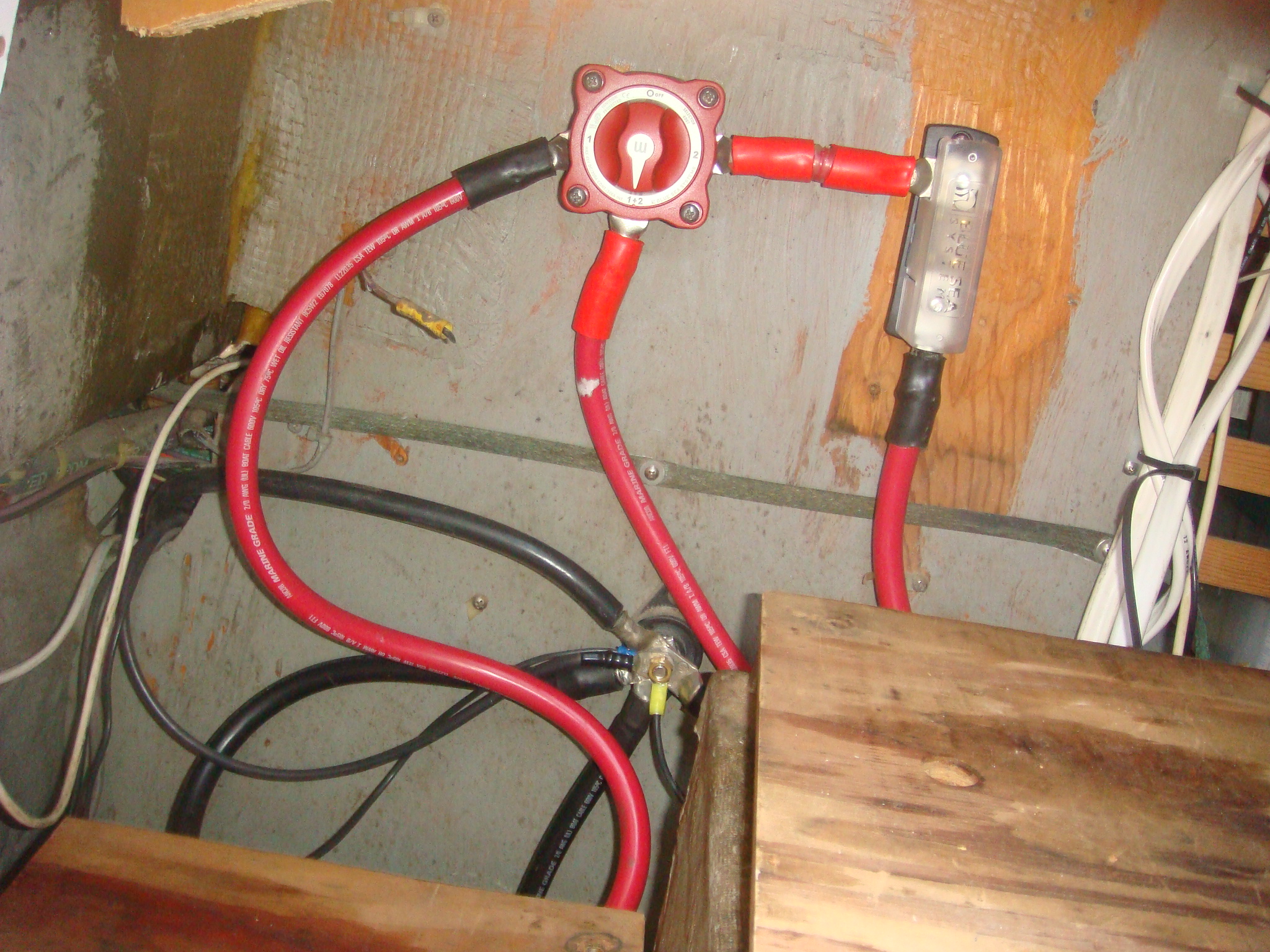
possible, so it is almost 100% that it will happen sometime.The reason I oriented the switches in this manner was to maximize the distance between the terminals on adjacent switches - to prevent contact between the circuits on two switches. Well it took over 6 years, but finally in 2011 an unsecured object in the locker hit the House battery switch and disconnected it. I immediately recognized the problem and corrected it. Gotta keep things that can move around out of this locker or change the type of switch. The loose red cable is for the LectraSan sewage treatment system and was connected to the COMMON terminal on the old switch. This cable is now connected to the START switch so the Start Battery will be used to supply the high current demand of this unit. Previously turning on the LectraSan would cause the autopilot to go bonkers. In 2007 the ElectraSan was removed from the boat. The large orange cable running across the from of the locker is the Starter/Alternator Output cable from the engine compartment. This cable is connected to the Battery side of the START switch so that the alternator will always charge the START battery. A Battery Combiner will be added to electronically connect the batteries during the charge process and provide a charging current for the House Battery.. |
|
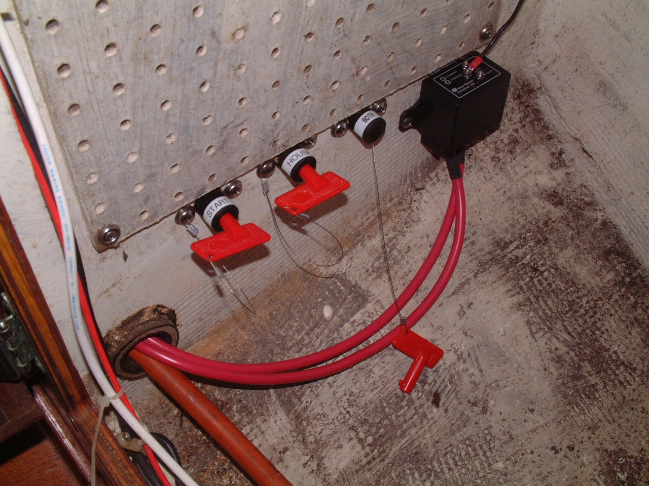 The switches are labeled (from left to right)
START, HOUSE, and BOTH.
Notice
that the BOTH switch is in the open position. This is the normal position
to isolate the starter circuit from the house circuits. If the I need to
use the HOUSE battery to start the engine, I would open the START switch
(disconnecting that battery) and close the BOTH switch. That would connect
the starter circuit to the HOUSE battery, while it continues to supply
current the house circuits. Similarly I can use the START battery for the
house circuits by opening the HOUSE switch and closing the BOTH switch. I
would only combine both batteries (by closing all switches) if I were trying
to start the engine and both batteries are badly discharged. The switches are labeled (from left to right)
START, HOUSE, and BOTH.
Notice
that the BOTH switch is in the open position. This is the normal position
to isolate the starter circuit from the house circuits. If the I need to
use the HOUSE battery to start the engine, I would open the START switch
(disconnecting that battery) and close the BOTH switch. That would connect
the starter circuit to the HOUSE battery, while it continues to supply
current the house circuits. Similarly I can use the START battery for the
house circuits by opening the HOUSE switch and closing the BOTH switch. I
would only combine both batteries (by closing all switches) if I were trying
to start the engine and both batteries are badly discharged.The switch keys are secured to the switch bases with wire fishing leader. |
|
| Battery Combiner | |
| In the picture above, the black box to the right of the switches is the Battery Combiner. The red cables connected it to each of the battery-side terminals on the START and HOUSE switches. When the alternator begins to charge the START battery this switch will be open send the full output of the alternator to the START battery. Once that battery reaches 13.3 VDC the switch will close connecting the positive terminals of the two batteries together. At that point the alternator output is shared by both batteries. When the engine is shut down and the charging current ceases (reducing the START battery to less than 13.3V) the switch will open isolating the two batteries. | |
The battery combiner worked flawlessly for
over a year. Then after spending the winter in Cascais, PT I discovered it
had failed on our way to Gibraltar. I'm not sure when the unit
failed or what caused the failure. I purchased the West Marine Combiner
based on the charging current that would have to be supported. The max
output from my alternator is about 45A and the max output from my battery
charger is 40A.
 Specs
on the combiner said it should easily handle these currents. What I believe
might have happen is when my batteries failed over that winter (see below)
the START battery was no longer capable of providing the current required by
the starter motor. When I started the engine dockside with the battery
charger on, the batteries were combined and the starter motor current was
supplied by both batteries with the current from the HOUSE battery coming
through the combiner. Due to low voltage this current likely exceeded the capacity of the
combiner and caused it to fail. Specs
on the combiner said it should easily handle these currents. What I believe
might have happen is when my batteries failed over that winter (see below)
the START battery was no longer capable of providing the current required by
the starter motor. When I started the engine dockside with the battery
charger on, the batteries were combined and the starter motor current was
supplied by both batteries with the current from the HOUSE battery coming
through the combiner. Due to low voltage this current likely exceeded the capacity of the
combiner and caused it to fail.
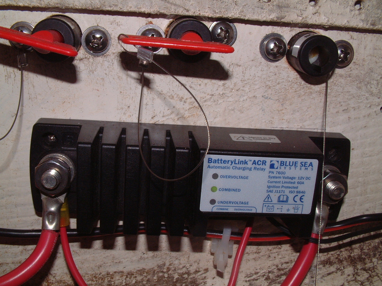
While in Gibraltar I ordered a replacement, the Blue Seas 7600 and had it sent to my brother who would join me a few weeks later in Almerimar. This combiner is rated for 60A continuous duty and 120A for up to 2 minutes. At the time I had not completed my analysis of the failure, and just bought what I thought was the heaviest duty combiner in the West Marine catalogue. By the time my brother arrived with the new combiner, I realized that this unit may not be any more robust than the unit I replaced I decided to put off the combiner installation until I was in my winter berth in Lagos, PT and could determine if it was sufficient for my installation. Shortly after arriving in Lagos I did install the new combiner (picture above). The intention was never to have the combiner sustain the starter motor load from the HOUSE battery, the BOTH switch was intended for that purpose. The problem was how to prevent that load coming onto the combiner should the batteries fail again. For that purpose I have ordered a switch for this combiner to allow me to turn it off when connected to shore power. I will bring that switch back from my visit the states in November, 2006. In the meantime the combiner should have no problems as long as the batteries are in good condition. Another precaution is to always disconnect from shore power (or turn off the battery charger) a minute or so before attempting to start the engine. That should allow the START battery voltage to drop below 13.3VDC and cause the combiner switch to open. If I have a weak START battery I can use the mechanical switches to use the HOUSE battery to start the engine, or combine them. In either case the additional current from the HOUSE battery will not go through the combiner switch. Blue Seas does sell a combiner that is rated for starting current loads, but I have stayed with this combiner for several years and as of 2012 I have not installed the switch to manually turn the combiner off. |
|
| Recently (Nov, 2009) the manufacturer of the West Marine combiner (Yandina) contacted me about the failure through this website. They doubted the starting currently would have caused the combiner to fail as it is capable of handling momentary loads of over 1,000 amps. They also pointed out that they provide an unlimited lifetime warranty on the combiner. They would have replaced or repaired the unit under that warranty if I had contacted them. Figuring I had done something wrong I never investigated the warranty and I did not realize the how strongly the company backs their product. My loss. | |
|
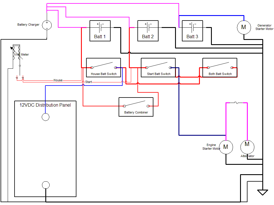
The drawing on the right is a schematic of the battery and charging circuits on
Sarah, showing the three battery circuit switches (HOUSE, START, and BOTH)
and the battery combiner switch. Updated on 7/28/2009 to show removal
of LectraSan system.
The schematic does not reflect the battery reconfiguration described further in this page. Also shown are the four main load circuits connected to the batteries.
You can view a full-sized image of the schematic by clicking on the thumbnail drawing. |
 12VDC Schematic |
|
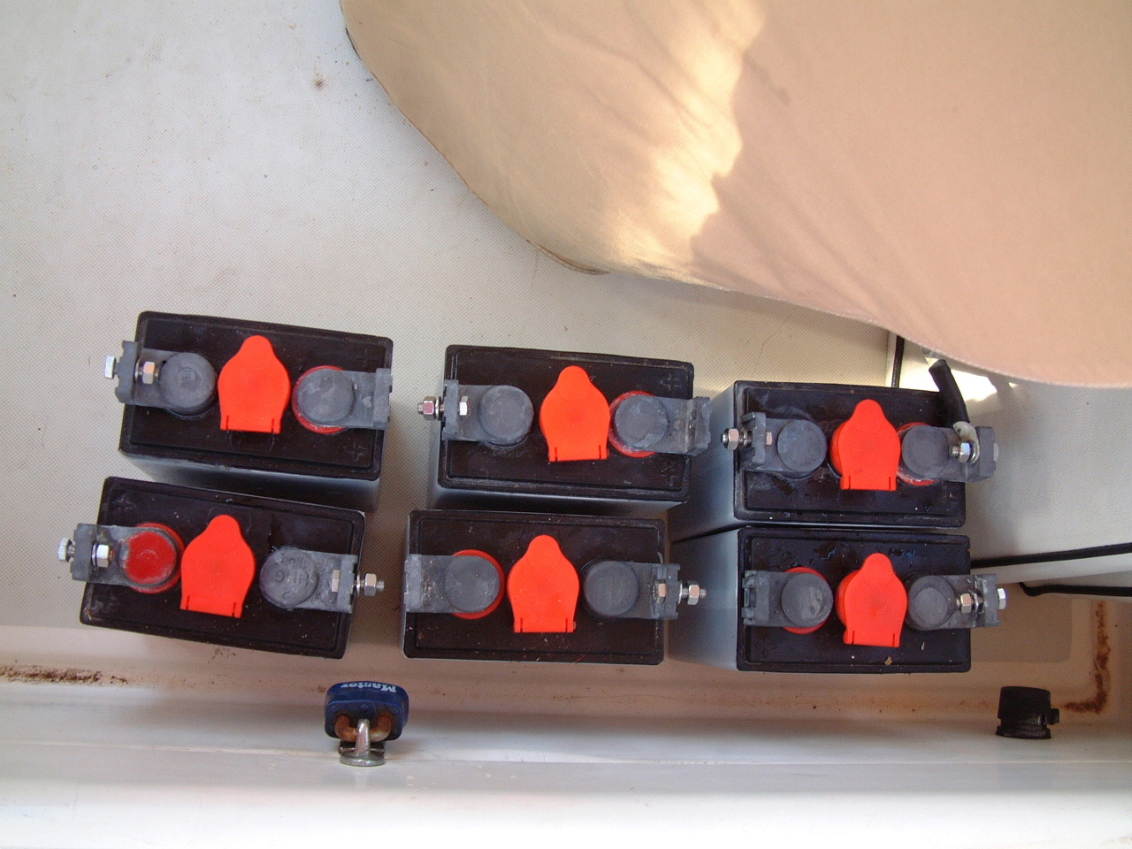
With the battery reconfiguration the battery banks configurations are as follows:
|
|
| Combiner Wiring Issue | |
|
Over the years since I installed the combiner I have been repeatedly advised that I have the combiner wired backwards. The alternator charging current goes directly to the Start battery and the House battery bank does not receive any charge until the Start battery voltage goes above 13.3 VDC. I incorrectly reasoned that it was more important to re-charge to Start battery before charging the House bank, but the real reason for this configuration is that it required no change to the standard Alternator wiring harness. There are several reasons why that reasoning is not correct.
My wiring did not cause any problems for the first six years of operaton because my Start and House batteries were identical and there were no major loads on the House bank. Then things changed:
The result of those changes was I began to experience the cycling problem
described in the Blue Sea paper. When I left for the Bahamas in
January, 2014 I experienced significant battery charging problems, especially
when using the windlass to haul in the anchor. I also had a couple of
failing batteries in my House bank and I attributed the problem to those
failures. Only later did I learn of this cycling problem. The
failing batteries didn't help, but the real problem was having the
alternator output going directly to the Start battery rather than the House
bank. |
|
| Battery and Battery Box Failure | ||
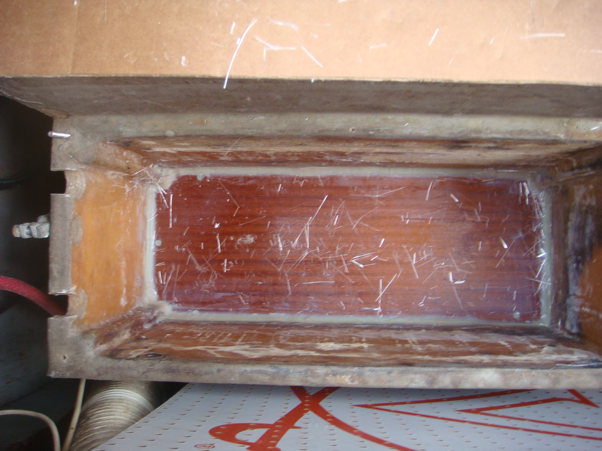
| While sailing across the Atlantic from Florida to Portugal I discovered that the bottom of the outboard battery box had broken loose, the battery had dropped several inches and was resting on the inside of the hull. I discovered this problem while Sarah was moored at Capt. Smoke's Marina in St. Georges, Bermuda and we were in final preparations for our departure for the Azores. We had already spent a week in St. Georges getting the stern rail fixed and I was not anxious for a prolonged stay in Bermuda to repair the battery box. |
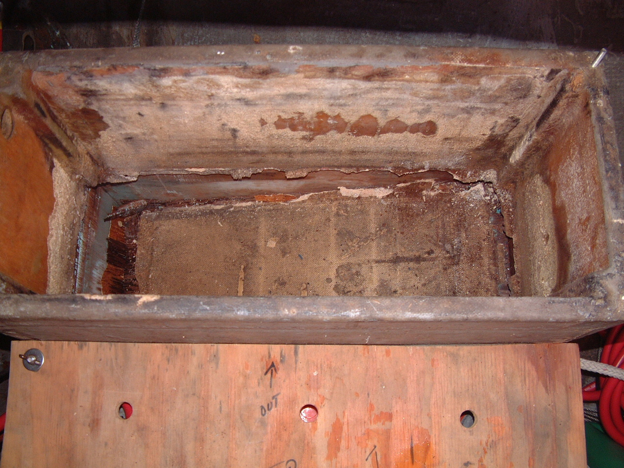 Broken Bottom in Outboard Battery Box |
|
| Although the built-in box had failed, the battery was still secured in the plastic case. There was little or no chance of the electrolyte spilling. Although the battery had dropped down several inches and was at a slight incline it would not move and I felt there was no threat of producing abrasion or an impact load on the hull. Therefore I elected to depart for the Azores with the battery box in this condition, and we completed the cruise to Cascais, Portugal with no issues from this situation. | ||
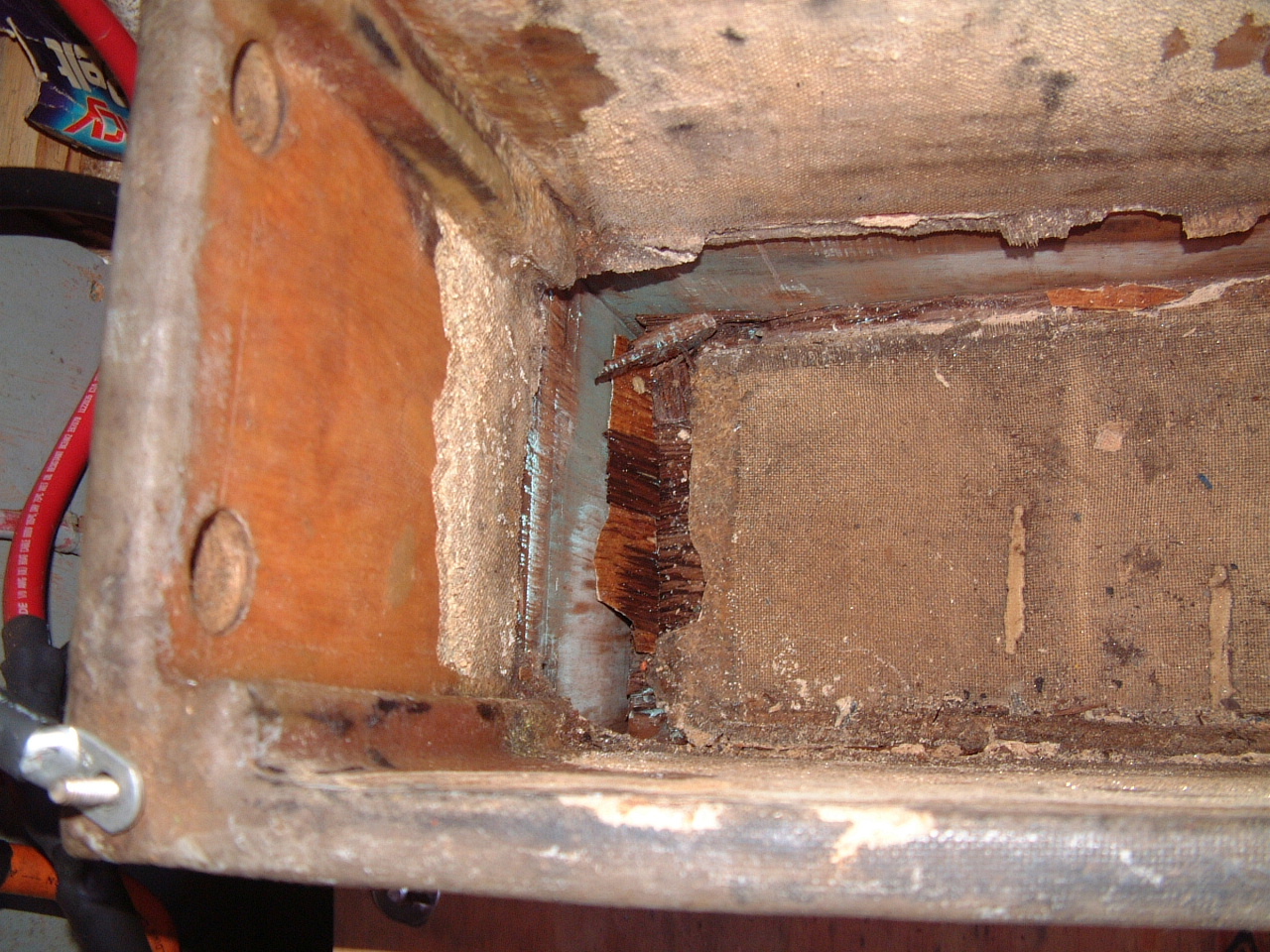 Bottom Separated From the Sides |
The picture on the left shows the forward end of the box where the bottom has dropped about one inch lower than the aft end of the box. | |
| Although we sailed to Portugal without any further issues from the battery installation, I did manage to kill at least one of the batteries once we reached Cascais. I had purchased new Rolls Batteries while in Florida. These are their new modular batteries with removable cells. The pictures on the right show the START battery after I removed it to repair the broken battery box. |
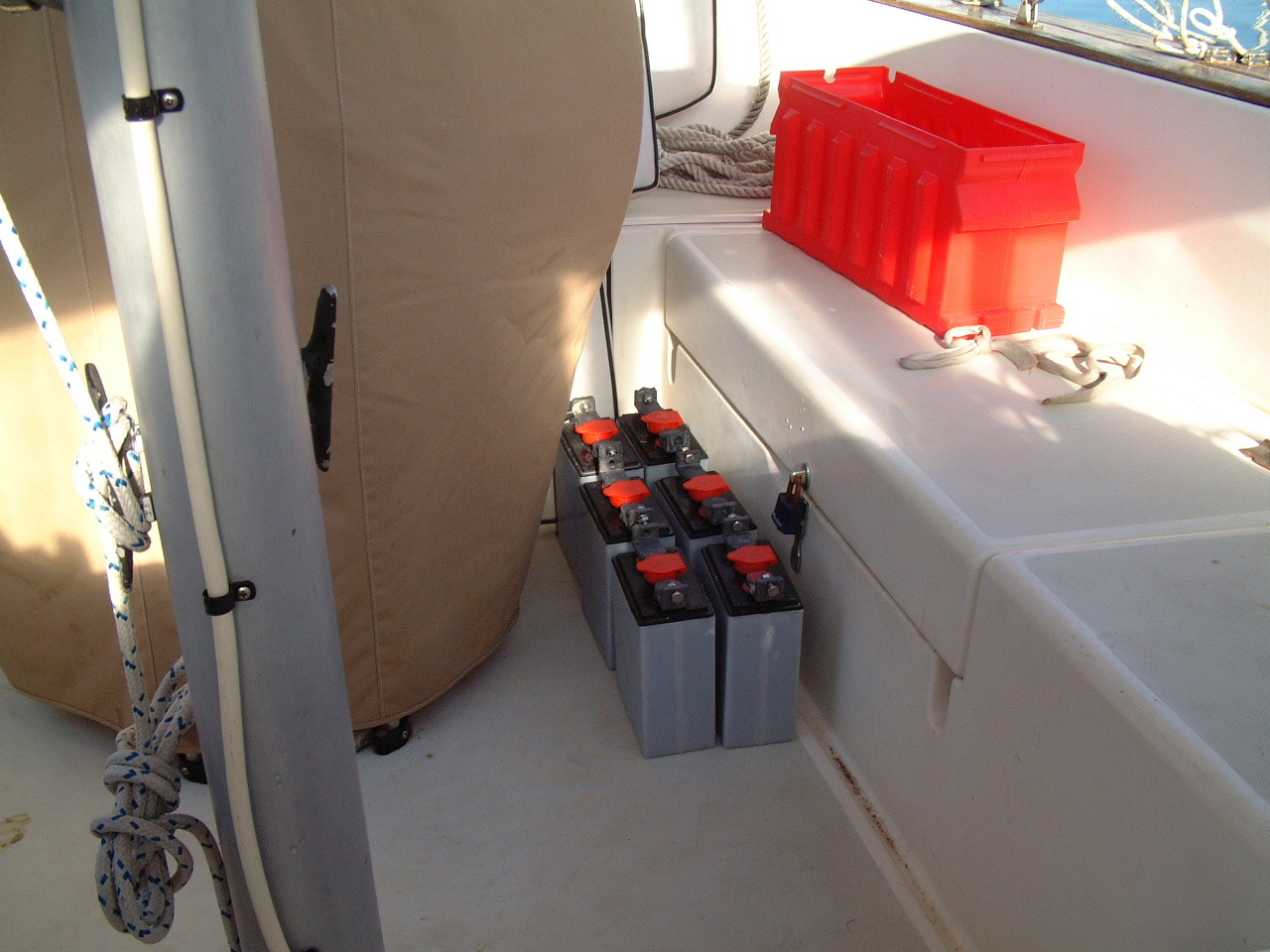 Removed Rolls 12 VDC Battery |
|
|
While under sail, if the batteries need charging, I normally ran the Northern Lights Generator rather than start the main engine to re-charge the batteries. The re-charging is performed by the Xantrex Battery Charger installed on Sarah. Initially I found that it took a very long time for the battery charger to re-charge the batteries. This battery charger is one of the newer "Smart" chargers and it works with an optional temperature sensor on the battery to regulate the charging process. I did not purchase this sensor for the installation on Sarah. | |
| A battery charger is inherently slower to re-charge a battery than the
engine alternator, as the charger is designed primarily for shore side
operation where the boat may be left on shore power for a week, a month or
longer. However the fuel savings by using the generator rather than the
engine (as well as the reduced engine wear) more than made up for the slower
charge rate. Still I wanted to reduce the amount of generator run time
as much as possible. Because I didn't have the optional temperature
sensor, the installation manual recommended that I set the temperature
switch on the charger to "Hot". The other settings are "Warm" and
"Cold". The charger delivers maximum current to a cold battery and
minimum current to a hot battery. Therefore the "Hot" setting (without
a sensor) is the "safe" setting to prevent battery damage. Since we
were running the charger for relatively short periods I reasoned that the
temperature of the battery was not a significant issue and while we were
sailing to the Azores I changed the switch from "Hot" to "Cold". This
delivered a much higher charge current to the batteries and reduced the
generator run time significantly. Unfortunately I immediately forgot about this switch setting for the rest of the voyage and left it on "Cold" even when we were tied to a marina dock running on shore power. This probably did no major damage while we were in the Azores, but when we arrived in Cascais I put Sarah on continuous shore power for several months. I was on board for the entire month of September, then I returned to the states for the month of October. All this time the charger was pumping current into what it thought were "Cold" batteries, but in fact it was boiling the electrolyte in some very hot batteries. Shortly after I returned to Sarah in November I noticed that even with the battery charger on, the HOUSE battery was showing low voltage. I checked the battery and found no visible electrolyte in any of the cells. The START battery also appeared dry. Then I remembered the temperature switch and moved it back to the safe "Hot" setting. Rolls Batteries have a deserved reputation for taking abuse and repeated discharge, but no battery is designed to be run dry of electrolyte. Hoping I might have dodged a bullet I refilled both batteries with distilled water. They both returned to a full charge, but the house battery would not hold its charge for more than a few hours under any load. The start battery was able to support a small load (normal cabin lighting) for a 24 hour period, and although damaged seemed capable of fulfilling its role of providing sufficient current to start the main engine. So before I resume cruising I must replace at least the HOUSE battery. While the battery box was being repaired I removed the batteries and tested each cell. Because of the modular construction of the Rolls Battery I was able to select the strongest cells for the START battery. |
||
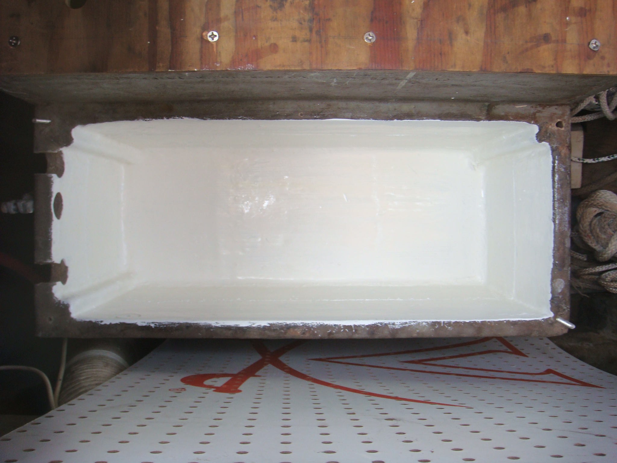
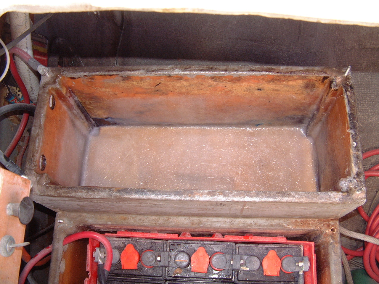 Repaired Battery Box |
Repairing the battery box looked like a difficult and messy job. Fortunately there was crew from Poland working on a 55' catamaran at our dock in Cascais at the time. One of the crew was an expert with fiberglass and offered to repair the box for me. An offer I immediately accepted. On the left is the repair to the box. | |
He first ground down the inside of the box to set it up for the glass work, and removed the old bottom. Then he glassed in some cleat stock to provide the support for the new bottom. Finally he glassed in the new bottom. He wanted to gel coat the inside of the box to make it look professional. I declined as it would make me want to finish off the other box as well. Everything looks good. In the picture the glass is still setting up. In a few days I will put the battery back in the box. Right now (Mar, 2006) I'm agonizing over whether to replace both batteries or just one and use the current 12 cells to come up with the best 6 cells for the other battery. Rolls Batteries are very expensive in the states. In Europe they are outrageously expensive. Also there is no Rolls dealer in Portugal, so I will have to pay shipping from the UK. I tried to find a good source of deep cycle batteries here in the Lisboa area, but no one seems to offer batteries in the class of Rolls or Trojan. Eventually I replaced both batteries with 4D batteries from Tudor, a European manufacturer. Those batteries lasted all summer in the Med and on the sail back to the USA in 2007. They finally started to fail in 2008 and were replaced with Deka 6-volt batteries. The Dekas were replaced with Trojan T105s in 2014. |
||
| 2nd Battery Box Repair | ||
| Over the winter of 2012, in Jacksonville, I noticed that the bottom of the inboard battery box had also broken loose. I waited until the next summer to have that box repaired at Zahniser's Yachting Center in Solomons, MD. |
 Bottom Removed and Ready for Rebuild |
|
 Cleat Stock in Place |
After removing the bottom and prepping the sides for the new bottom, cleat stock was glassed to the sides. The cleat stock will support the new bottom for the box. | |
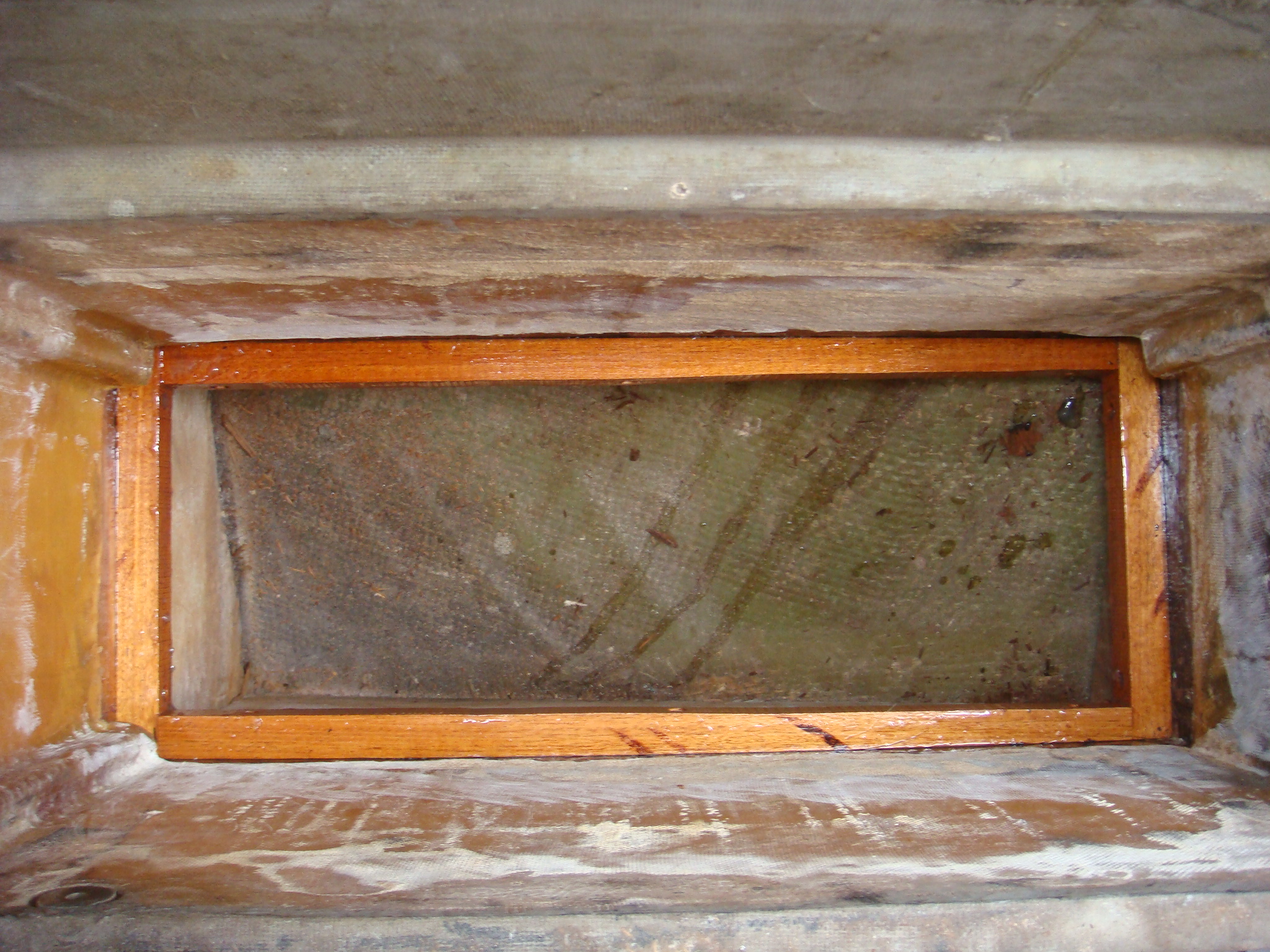
| Then a plywood bottom was glassed in place. |
 Bottom Glassed in Place |
|
 Battery Box Rebuild Complete |
The repair was completed when the entire inside of the box was glassed over. | |
| Additional Breaker Panel | ||
 Sarah
has the original Marinetics electrical panel installed when the boat was
built by Pearson. This is a large panel with one column of 120VAC breakers
(yellow) and two columns of 12VDC breakers (Red and White). When I
purchased the boat the previous owner had already overrun the number of
circuit breakers and had multiple circuits on many breakers. I consolidated
several of those circuits and reduced the number of circuits on several of
the breakers, but overtime I have added a number of circuits and those had
to go on one of the existing breakers. Sarah
has the original Marinetics electrical panel installed when the boat was
built by Pearson. This is a large panel with one column of 120VAC breakers
(yellow) and two columns of 12VDC breakers (Red and White). When I
purchased the boat the previous owner had already overrun the number of
circuit breakers and had multiple circuits on many breakers. I consolidated
several of those circuits and reduced the number of circuits on several of
the breakers, but overtime I have added a number of circuits and those had
to go on one of the existing breakers.Finally in the fall of 2006 I had to do something. I wanted to add a few more circuits and I wanted to isolate a few of the existing circuites, but all of the existing breakers were in use. For a number of years I've had a Blue Seas 12VDC Breaker Panel in my parts bin for just this purpose, but I've never gotten around to installing it. Now was the time. The previous owner had installed a stereo speaker on the electrical panel, which I removed shortly after purchasing Sarah. That left a large round hole in the panel (picture on the left), which for years I covered with a thin piece a Teak plywood. This was the obvious place to put the panel, something was needed to cover this hole. |
||
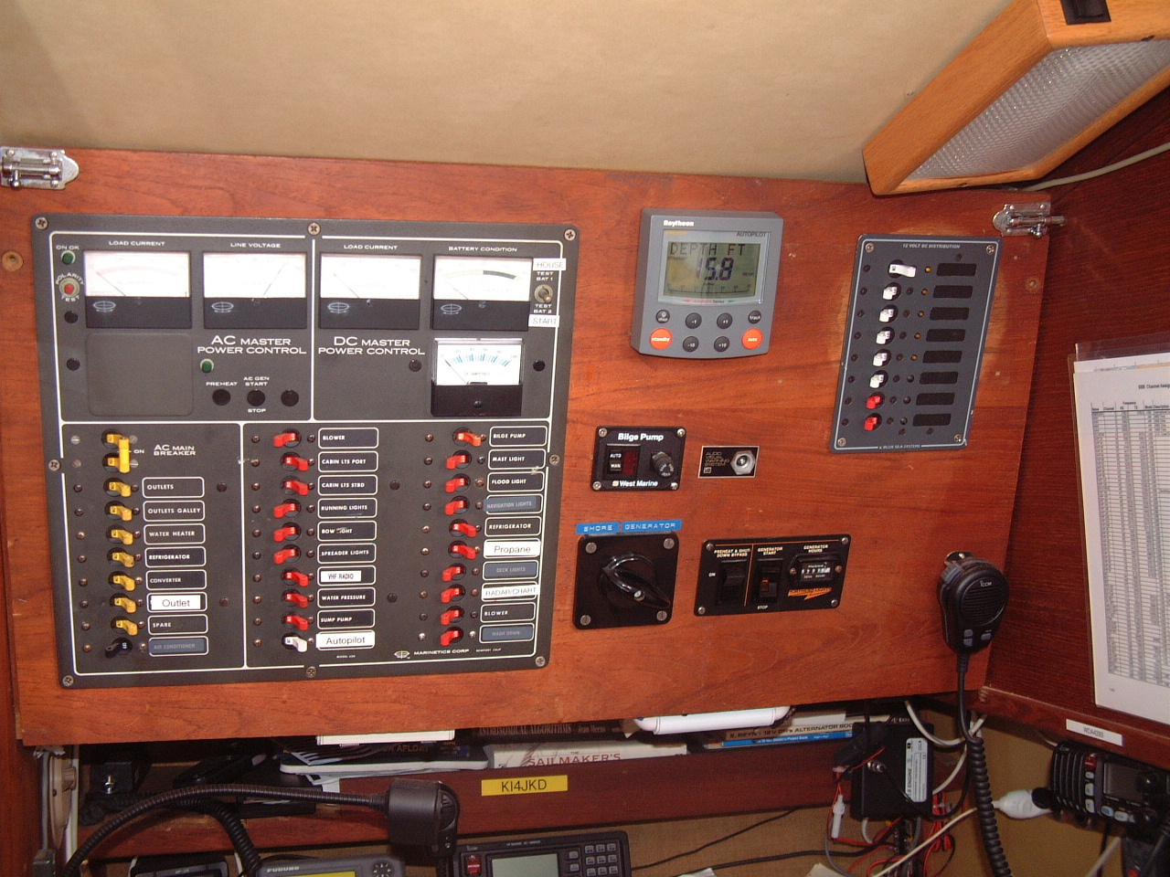 On
the right the new breaker panel has been installed. One nice feature of
this panel are the small LED next to each switch that show which circuits
are ON. On
the right the new breaker panel has been installed. One nice feature of
this panel are the small LED next to each switch that show which circuits
are ON. |
||
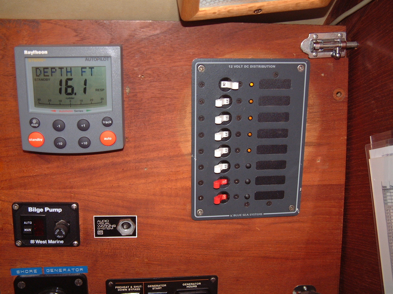 The
first circuit I added was power for my Raymarine SeaTalk instruments. I
have always provided power to the SeaTalk bus from the autopilot course
computer.
This was the simplest was to wire the SeaTalk instruments. To turn the
instruments on all I had to do was turn on the autopilot. This worked well
for years, although I had to keep the autopilot powered up to have
instruments when sailing even when I was using the Monitor windvane to steer
the boat. In Standby the autopilot draws very little current so this really
wasn't a problem in itself. However, I had seen some anomalies in the
instrument operation (e.g., the instrument lights dimming or turning off on
their own) and I thought it might be prudent to provide power to the
instruments separate from that to the autopilot. The
first circuit I added was power for my Raymarine SeaTalk instruments. I
have always provided power to the SeaTalk bus from the autopilot course
computer.
This was the simplest was to wire the SeaTalk instruments. To turn the
instruments on all I had to do was turn on the autopilot. This worked well
for years, although I had to keep the autopilot powered up to have
instruments when sailing even when I was using the Monitor windvane to steer
the boat. In Standby the autopilot draws very little current so this really
wasn't a problem in itself. However, I had seen some anomalies in the
instrument operation (e.g., the instrument lights dimming or turning off on
their own) and I thought it might be prudent to provide power to the
instruments separate from that to the autopilot.I had also added a number of low power electronics to my navigation station (SSB Antenna Tuner, NAVTEX, AIS, etc.) that had been added to other circuits. The new breaker panel would allow me to re-arrange these circuits in more logical and manageable configuration. |
||
| Upgrade Battery Configuration | ||
|
Although I have replaced the batteries on Sarah (West Marine AGMs, Rolls,
Tudor, and Deka) many times in my twelve years of ownership (as of 2012),
added a combiner, and replaced the
battery
switch arrangement. The basic cabling has remained unchanged.
This is still the original 2/0 welding cable installed when Pearson built
the boat. So just the fact that this cable is over 30 years old made
me want to replace it with heavily insulated and tinned marine-grade wire.
I also wanted to reconfigure the batteries to provide more capacity on the
house bank. For several years I've wanted to add 12VDC refrigeration
to the engine-drive and AC units installed on Sarah. This would allow
me to use other than fossil fuel as the energy source for the compressors.
The first step down this road is to upgrade the capacity of the house bank
to allow longer periods between charging the batteries. Sarah has the original glassed in battery boxes in the starboard cockpit lazarette. As of 2011 I had 2 Deka 6-volt batteries in each of the two boxes. One battery set is normally used for the house loads and the other set for starting the main engine. I can combine the battery banks or use a single bank to support both the house and starting loads. In April, 2011 I started a project to reconfigure the batteries. |
||
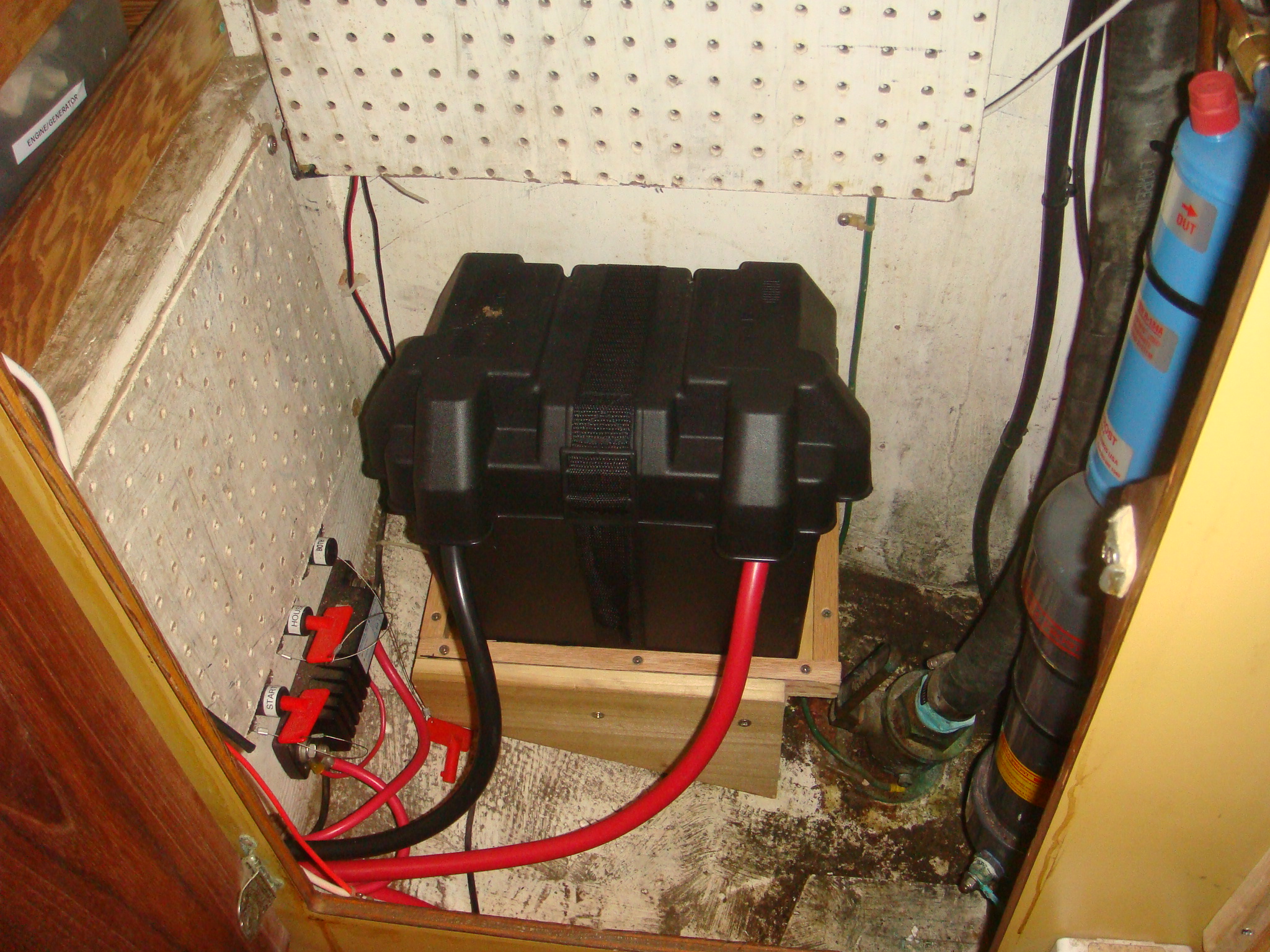
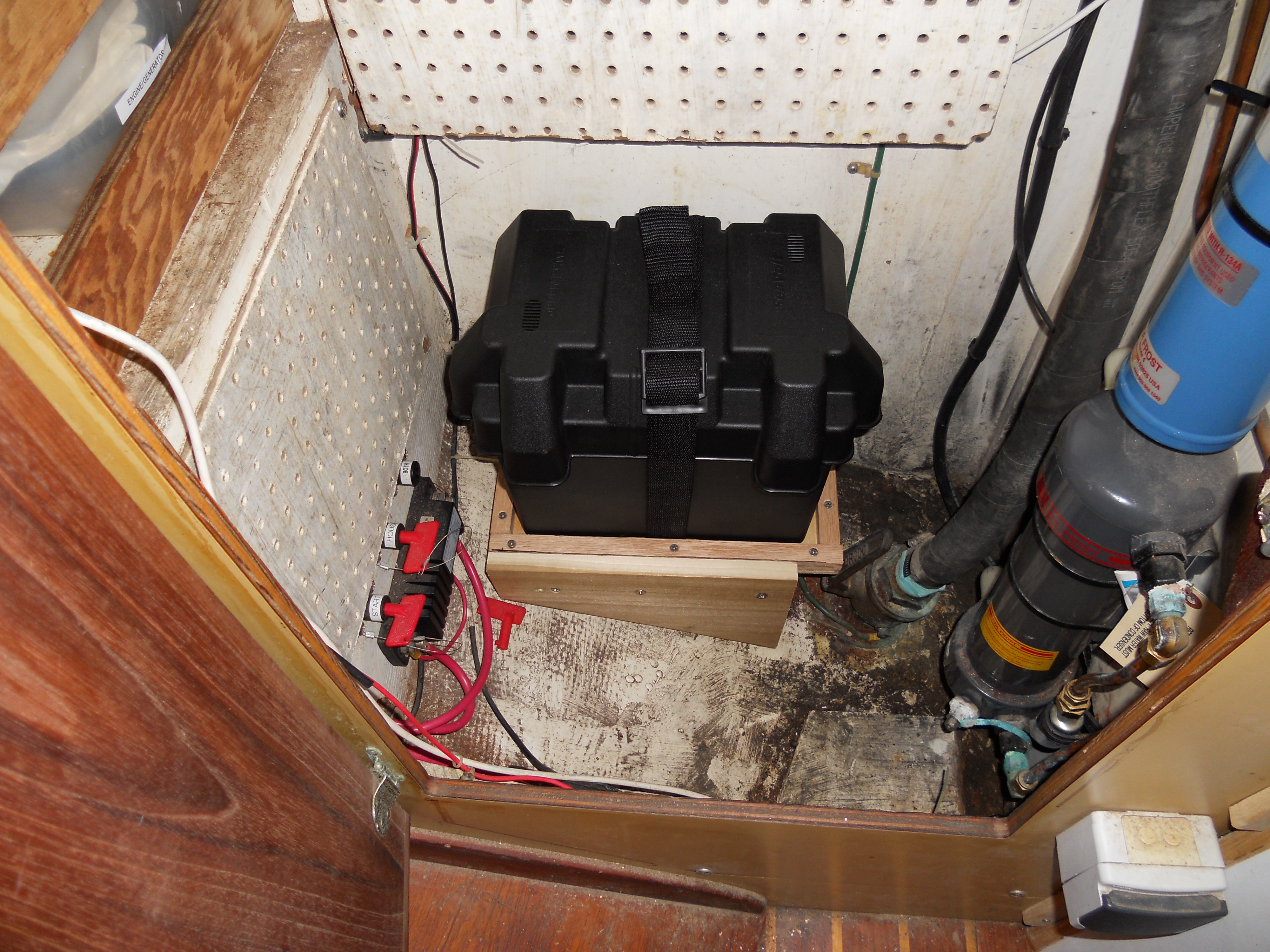 Start Battery Installed in Hanging Locker |
The first step on this reconfiguration was to build a shelf in the hanging locker in the aft cabin for the Group 24 starting battery. In the picture on the left, the shelf has been installed and the battery box and battery secured to it. The battery has not yet been cabled into the system. Once I have cabled this battery for starting the engine I can begin to reconfigure the existing batteries as the house bank. | |
| One of the deficiencies of the existing battery wiring is that there is no fuse protection on the main feed to the electrical panel. I planned to use a battery switch to combine or isolate the two house battery sets, and I added a fuse block between the common terminal on the switch and primary House battery switch in the locker. In the picture on the right I have installed the switch and the fuse block on the bulkhead in the starboard locker. I next needed to cable the two battery banks to this switch and then run 2/0 cable from the fuse block to the house switch in the hanging locker. |
 House Battery Bank Selector Switch and Fuse Block |
|
 Stripper and Crimper for Battery Cable |
I
used Del City, an Internet electrical
supplier, for many of the components used in the battery configuration.
I also picked up two tools from this source, as shown in the picture on the
left. The black object is a battery cable stripper. Having used razor knives in the past to strip the heavy insulation off battery cables I really appreciate the way this tool works. The blue object is a hammered terminal crimper. I've used the flimsy rocker-type crimper in the past, and it works OK, but this tool puts a really strong crimp in the terminal. It is also a big target for the hammer blow. |
|
|
It has taken nearly a year, but in Feb, 2012 I resumed working on
this project. The first day I disconnected the previous start battery
in the cockpit locker from the switches in the hanging locker and removed
the Positive Battery cable. I then made up a Negative Battery cable
for the new Start Batter and connected that battery to the common Negative
terminal post in the cockpit locker (photo on the right). |
 Negative Battery Cable Connected to Start Battery |
|
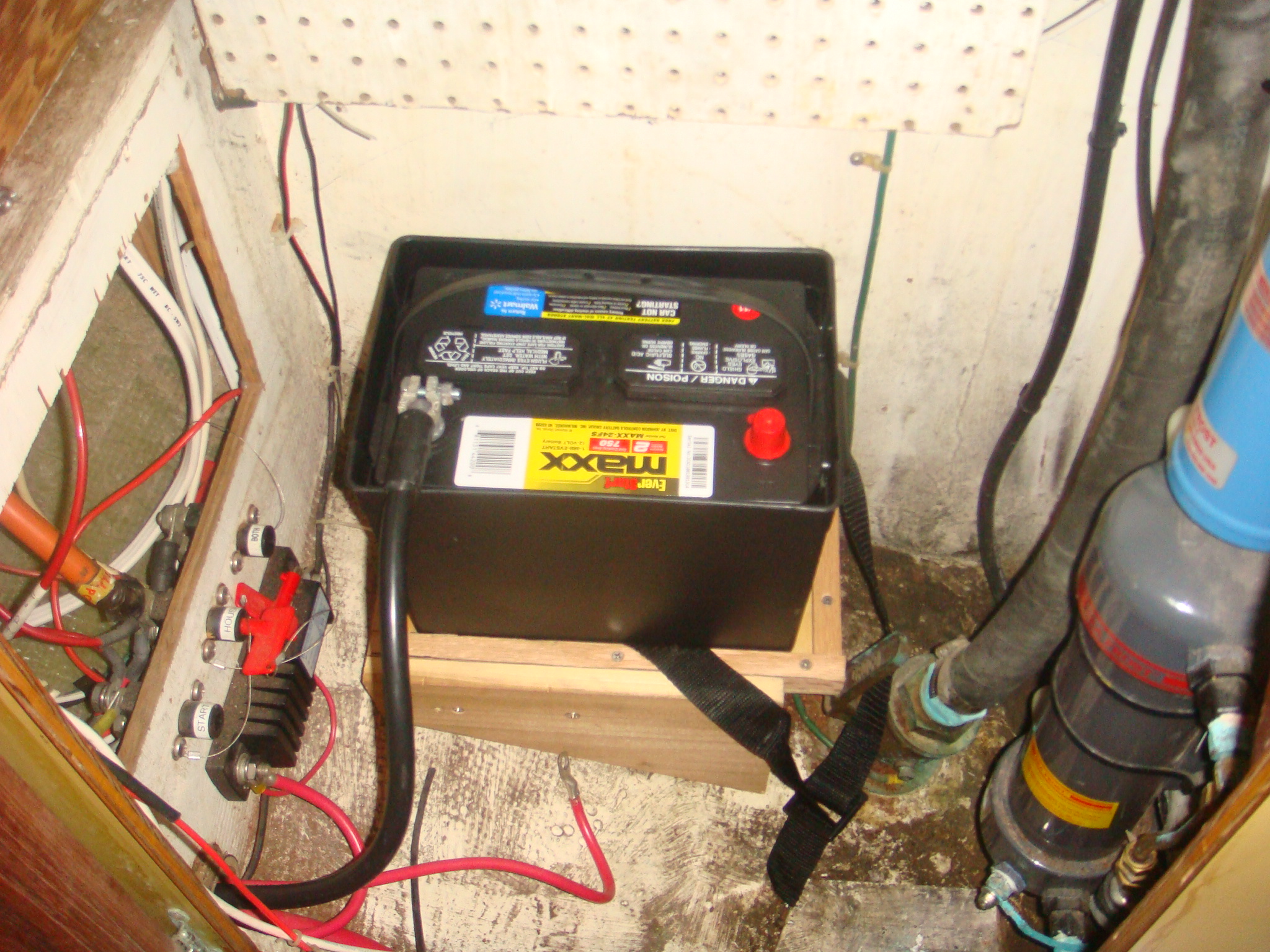
 Start Battery Wiring Complete |
The next day I made up the positive cable for the Start battery and connected it to the source side of the Start switch. The new Start battery was operational, however I had not tested it to start the engine. | |
| The old Start battery bank was then disconnected, and reconfigured to be 1/2 of the House bank. As part of this process I replaced all of the cabling between the two 6-volt batteries and the cables going to the positive load and the common Negative Battery post. The new cable is all 2/0 Ancor tinned marine cable. I also used the low profile battery terminals from Del City. The Deka batteries are actually too tall for the Pearson battery boxes. The previous battery terminals with a 3/8" vertical stud made them even taller. The battery box could not be fully secured. The low profile terminas have reduced the overall battery height by about 1". |
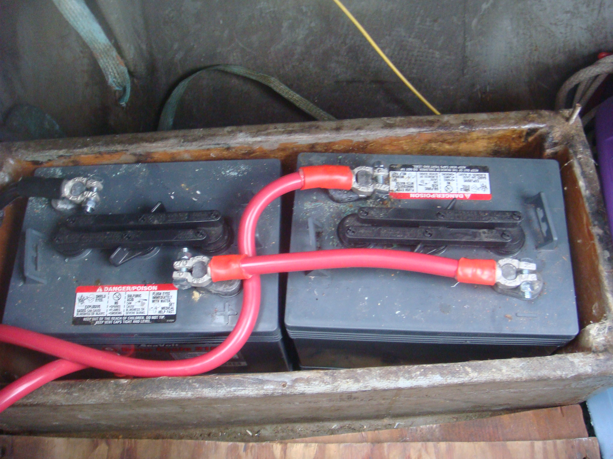 Reconfiguring the Old Start Battery |
|
 House Bank Battery Switch and Fuse |
The next job was to replace the Positive Battery cable from the House
On/Off switch in the hanging locker to the old House battery. The new
cable now runs from the House switch to the fuse block in the starboard
locker (photo on the left). The fuse is a 250 Amp ANL-type.
I will probably reduce this to a 100 Amp fuse in the future. I
just had the 250 Amp fuse in my parts bin. The battery selector is set on Battery 1+2 in the House Bank, which combines both battery sets (2 6-Volt each) into one House battery. |
|
|
This project is complete as of Feb 8. I had planned to switch the
battery combiner to charge the house batteries first, but I abandoned that
change for now. To run the alternator output to the House bank would
have required cutting open a cable harness on the engine. I decided
this was too much work for now. The alternator will charge the Start
battery before the House bank. This configuration has not caused
problems in the past seven years. I tested the battery combiner configuration after leaving the battery charger off for >24 hours. Before starting the engine the House bank was still around 12.5 VDC, so there was still plenty of reserve in that bank to go another 24 hours or more before recharging. When I started the engine the Start battery quickly went to 14.5 VDC. Within a minute the House bank started to receive a charge (combiner switch closed). Within another 3 minutes the House and Start banks were both charging at over 14 VDC. I thought I could live with this for awhile. Turns out I was able to live with the combiner wiring for a couple of years. Then I added an electric windlass and spent the winter of 2014 in the Bahamas. See the combiner wiring issue, above. |
||