Sailing Vessel (SV) Sarah
Sarah has a new owner as of 7/26/2021. There will be no more updates to these SV Sarah pages
Sarah has a new owner as of 7/26/2021. There will be no more updates to these SV Sarah pages
| Mechanical Upgrades |
| Contents: |
| Engine Work | |
Although
not really upgrades, during the first year I owned Sarah I had to have a
great deal of work done on the engine. Some of this was detected by the
pre-purchase survey, but the need for most of the work was not apparent
until I had put a few more hours on the engine. This work included the
following:
In preparation for the Bermuda cruise, I replaced all of the water and exhaust hoses on the engine. |
|
|
|
At the same time the water hoses were replaced I replaced the propeller shaft stuffing box with a PSS Shaft Seal. This is dripless, bellows type of seal. Many people view this device as less reliable than the conventional stuffing box, which may leak continuously, but lets in a small amount of water. Should the bellows fail on the PSS Shaft Seal, significantly more water will enter the boat. However I had one of these seals on my previous boat for nearly 20 years without any problems. |
|
At the time I installed this seal I was attempting to dry out the bilge
sump. I could see water dripping from near the pilot tube, but I
could not get a good view of the stuffing box to determine if it was the
source of the leak. Not knowing if it was an improvement or not,
I had the PSS seal installed. The picture on the right was taken
serveral years later, after I had a hatch cut in the cabin sole, just above
the pilot tube and the V-Drive jackshaft. I continued to have water in the bilge, so the seal did not solve that problem. Turns out the leak was from the rudder post, something I did not determine for several years. |
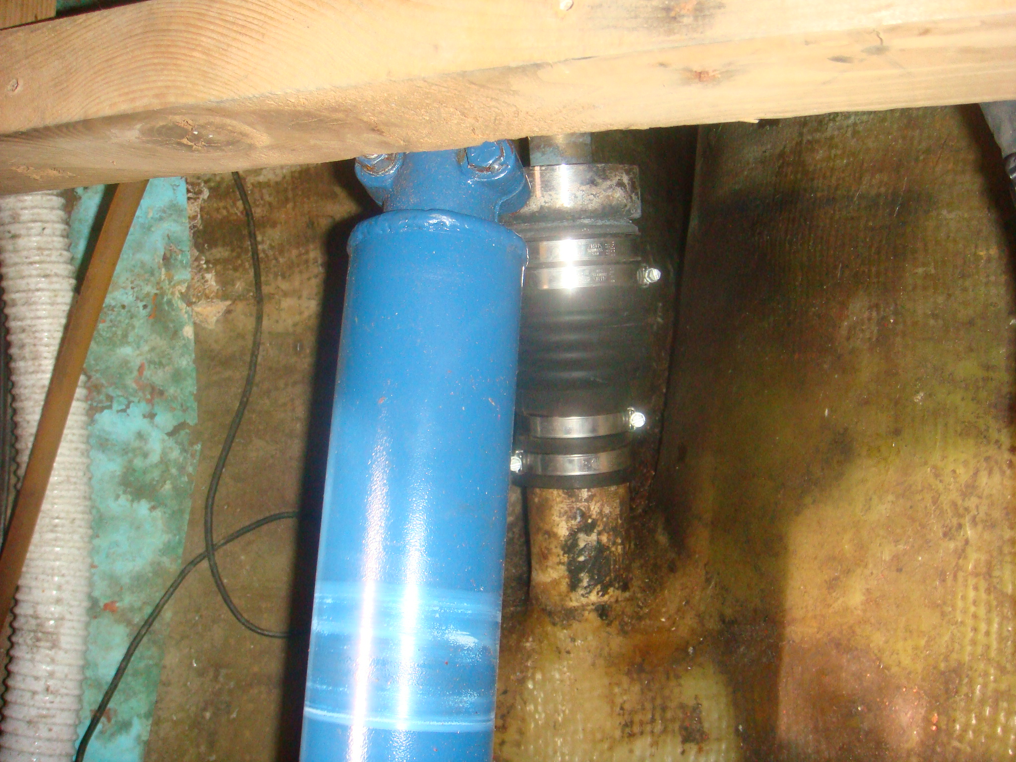 PSS Shaft Seal |
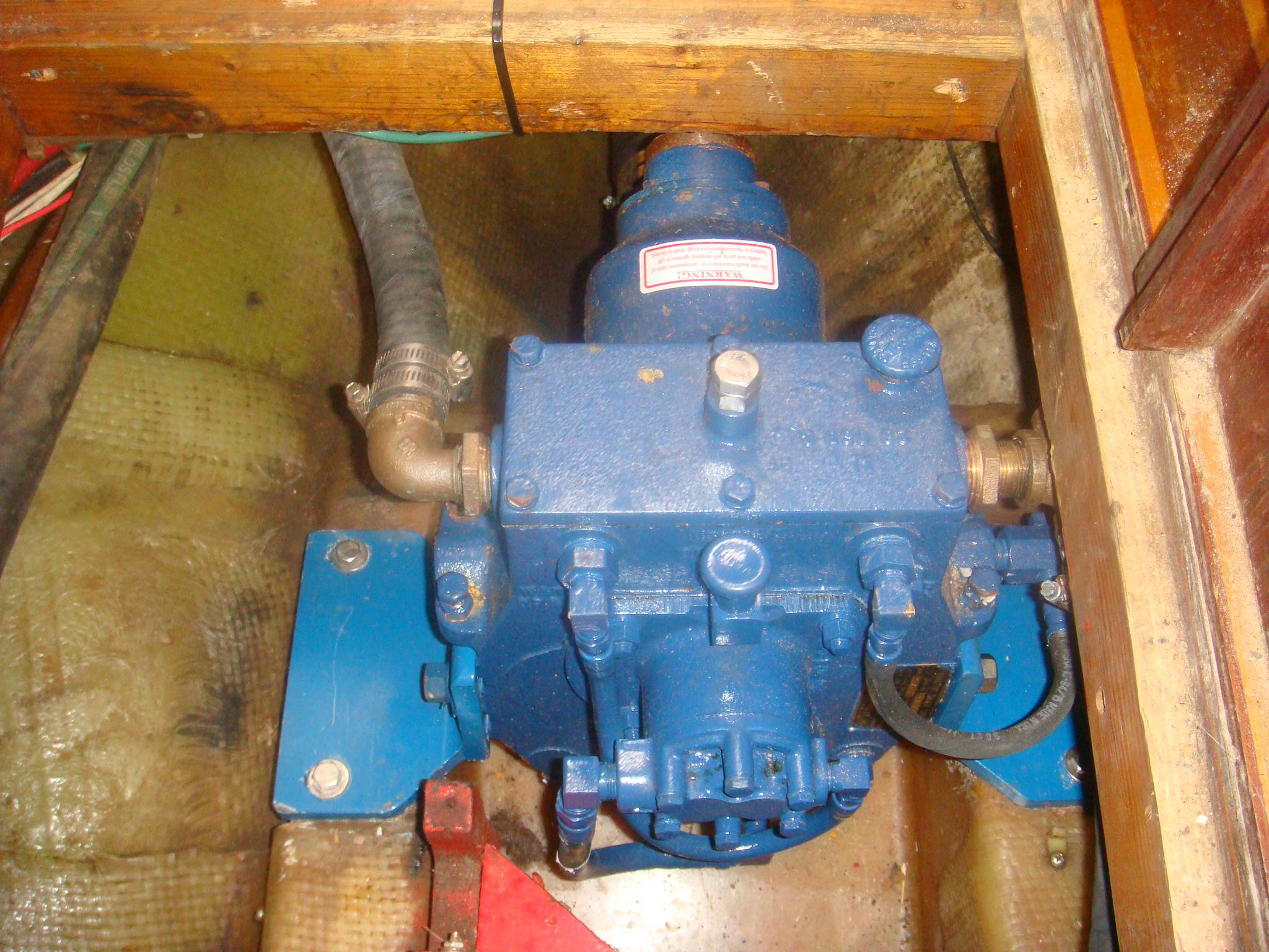 Walter RV-26 V-Drive |
In 2010 I replaced the original Walter RV-20 V-Dive with the Walter RV-26, shown on the left. This installation is described in a separate web page. |
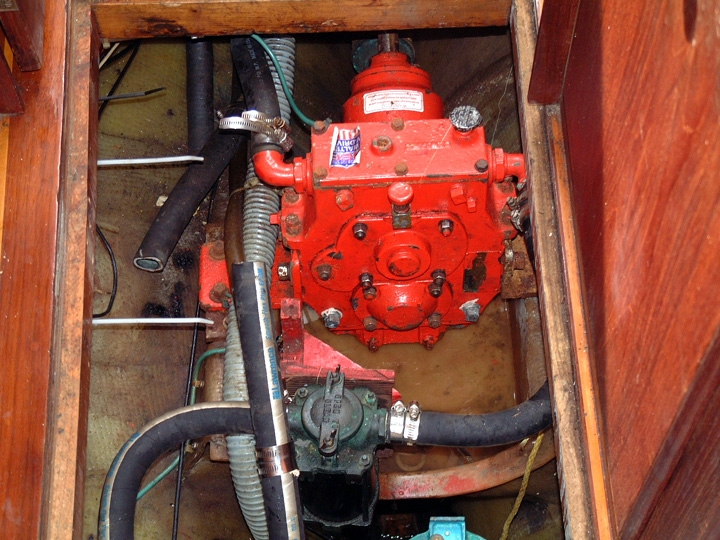
| On the right is the original, 30-year old Westerbecke 60 Engine. Other than having to replace a few very expensive parts (heat exchanger, fresh water pump, etc.) this engine has served me very well. I put several thousand hours on the engine since I purchased Sarah in 2000, including one summer of almost continuous motoring in the Mediterranean Sea. |
 Westerbecke W60 Engine and Paragon Transmission |
|
Finally after returning to the USA in 2007 it was time to retire this workhorse. In January, 2008 I moved Sarah to Zahniser's Yachting Center and started the process of replacing the engine and the fuel tank. I have set up a separate page to cover the details of this repower. The picture above was taken a few hours before the Westerbecke was removed from Sarah. |
|
| Fuel Filter Vacuum Guage | |
|
I routinely change the cartridge in the Racor 500 Filter at least once each year, but I've
often been concerned that the only way I can monitor the effectiveness of
the filter is to open it and pull out the cartridge. Even then I really
don't know if the cartridge needs to be replaced. If it looks pretty
dirty, I just replace it. I've long wanted some measure of the state
of the cartridge to insure I replace it before it starts to constrict the
fuel flow to the engine. A vacuum guage can be inserted in the fuel line to measure the degree to which the fuel pump is pulling a vacuum from the filter. These guages are not overly expensive, but the installation can be complicated. |
|
|
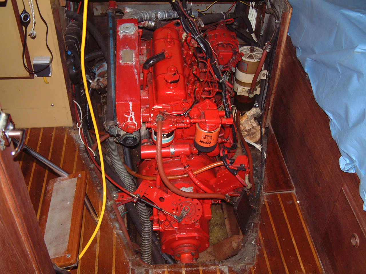
Recently on the Cruisers Forum one the posters recommended the R2D2 fuel filter guage from Fuel Fixers, Inc (shown on the right). This guage is a replacement for the T-screw that secures the cover on the Racor filter. So there is no need to splice a T into the fuel line for a vacuum guage. |
 R2D2 Fuel Filter Guage |
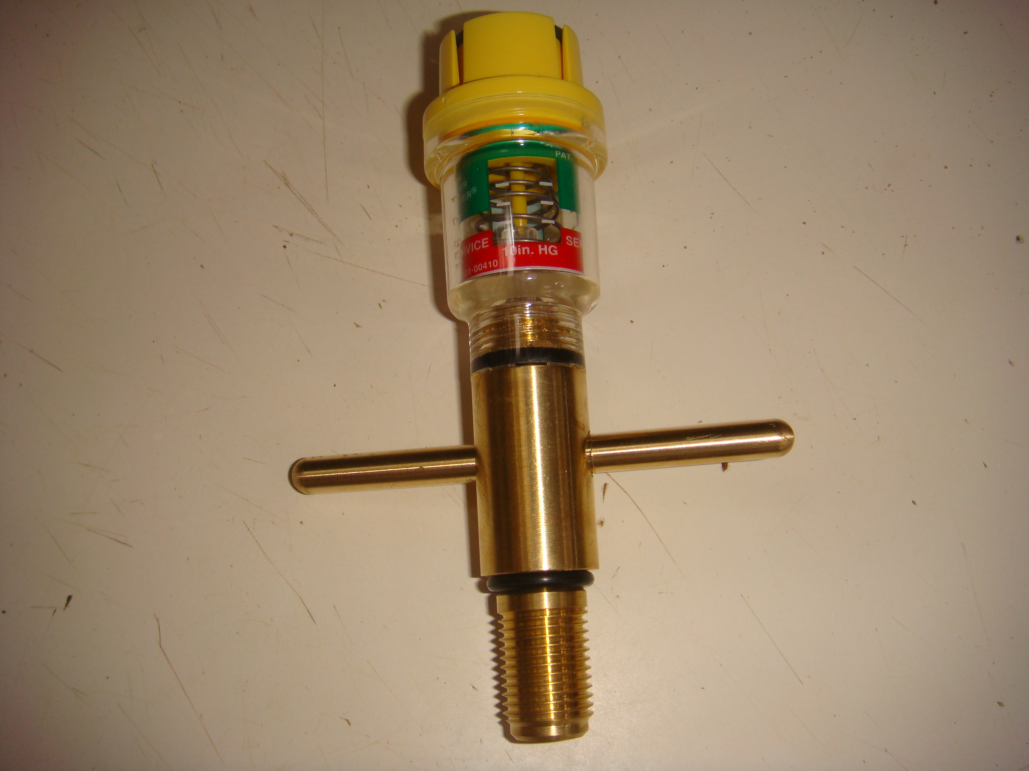
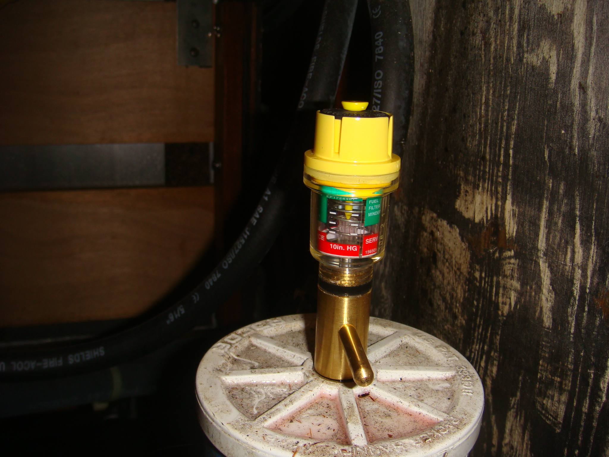
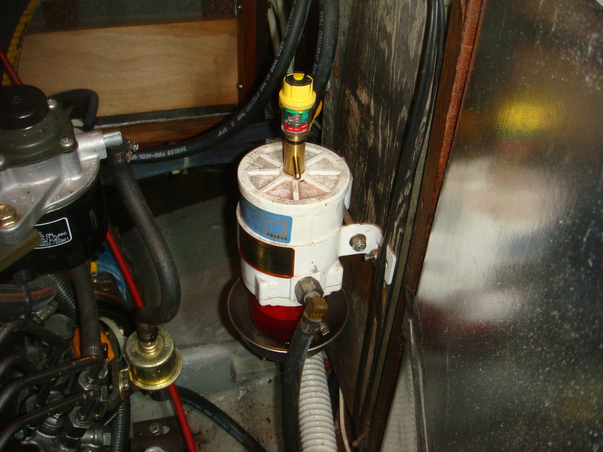 R2D2 Installed on Racor Filter |
In the picture on the left the R2D2 has been installed on my Racor filter. The engine was running when this picture was taken. |
|
The guage is the plastic top on the screw. As the filter fills with
debris in the fuel and the vacuum pulled by the fuel pump increases, the
spring loaded marker in the guage is pulled down through the green area
toward the red area on the guage. When the marker is at the bottom of
the green it is past time to replace the filter cartridge. The guage marker is held in place at the lowest setting during engine operation so it can be inspected after the engine has been shut down. The button on the top resets the guage after the filter has been replaced. |
 R2D2 Vacuum Guage |
| High Volume Sea Water Intake Manifold | |
| When I purchased Sarah she was equipped with both a Westerbecke 60 diesel engine as well as a Northern Lights diesel generator. Both engines were cooled by seawater from separate 1" seacocks and through hulls. Both systems required separate raw water strainers to prevent debris from getting into the seawater pumps. The seacocks were actually just ball valves screwed into the through hulls, which does not provide much support against a shear force. These valves did not appear to be high quality and showed signs of corrosion. Since I needed to replace those valves, I decided to reduce the number of through hulls by combining the two seawater circuits into one 1 1/2" seacock. | |
| The result is the seawater manifold shown on the right. The intake seacock is forward of this cabin sole hatch. The black water hose on the upper right connects the seacock and the raw water strainer. The manifold, on the left of the strainer, consists of a 1 1/2" "T" fitting connected to two 1" ball valves. The engine seawater is controlled by the valve on the extreme left of the hatch. The inboard valve serves the generator. Therefore although both engines are served by a single through hull, they can be run concurrently and their seawater coolant can be independently shut off and turned on. For more details on this upgrade see the Haul Out Tasks page. |
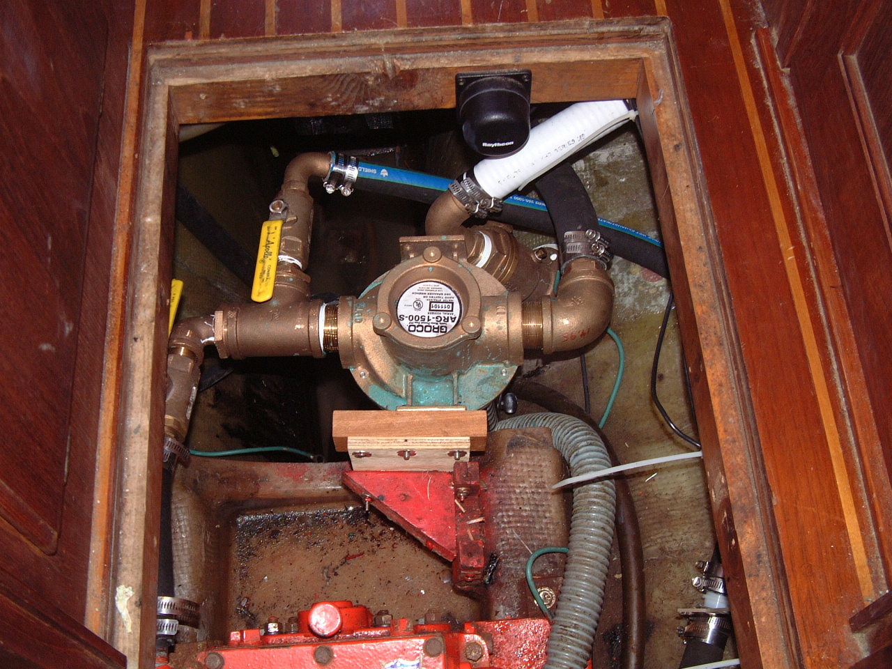 High Volume Seawater Manifold Serving the Main Engine and Generator |
| Low Volume Sea Water Intake Manifold | |
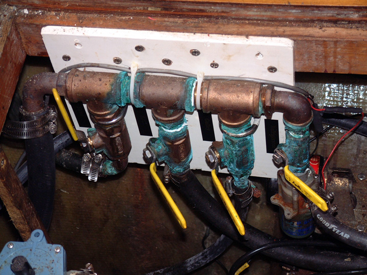 Original Low Volume Seawater Manifold |
In 2000 I replaced three individual through hulls and seacocks with a single through hull and seacock connected to a manifold that delivered low volume seawater to the head, galley sink, refrigeration and air conditioner. I was not satisfied with this location of the manifold as it intrudes into the hatch space too much. I decided to move it so that it is more flush with the edge of the floor board hatch. I also wanted to add a raw water strainer for this manifold. |
| On the right is the modified low volume manifold. The electric pumps for the refrigeration, air conditioner and shower drain are in the center and the Y-valve for the head discharge is at the bottom of the cabin sole hatch. You can see bilge pump and float switch at the bottom of the very deep (4') sump. See the Haul Out Tasks page for the trial and tribulations of this plumbing change. |
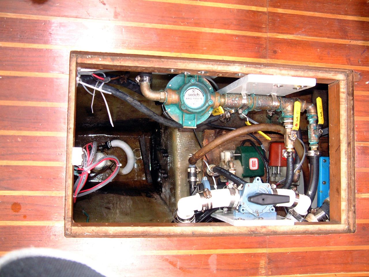 Modified Low Volume Seawater Manifold |
| Maxprop Propeller | |
| The original propeller on Sarah was a fixed 3-blade 20x10 propeller. This propeller had a lot of dinks and was showing its 20+ years of age. It also free-wheeled under sail whenever boat speed exceeded 4 kts. That put some extra of wear and tear on the transmission and V-Drive. This probably would not be significant for weekend sailing on the Chesapeake Bay, but for the extended off-shore voyages I have planned it could be problem. | |
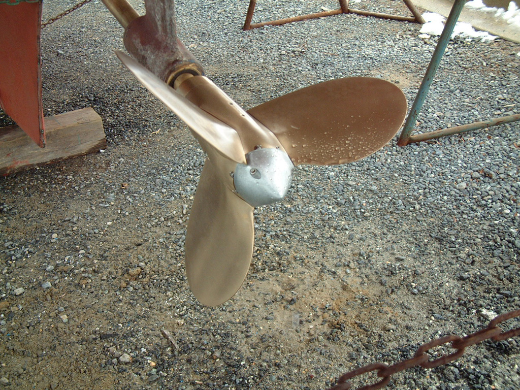 20" Maxprop Classic |
Therefore I replaced this prop with a 20" Maxprop. The alternative was to install a shaft lock to prevent the propeller from free-wheeling. The Maxprop does not work quite as well as I hoped in this regard, as the blades tend not to feather when I shut down the engine and start sailing. If I shut down the engine with the transmission in gear it will normally feather the blades and prevent free-wheeling. Reverse power with this prop is much more predictable for maneuvering around the dock. |
| Rudder Stuffing Box | |
| As long as I've owned Sarah she has had a wet bilge. In that time I've tried to find the source of the leak or leaks in vain. The leaks were so slight I could find no evidence of where the water was coming from. The leaks were slight enough that I rarely noticed the bilge pump coming on, but no matter how dry I pumped the bilge within a week it would be completely wet again. | |
|
I thought I could detect a leak from the propeller shaft stuffing box and I replaced that with a PSS shaft seal. A marine surveyor who had done work on the boat for the previous owner thought it was possible that a boat yard may have set the boat down on the aft portion of the keel, which is hollow. He thought the fiberglass may have cracked enough to allow in a small trickle of water. Before I left for Florida in 2004 I had the lower portion of the keel re-glassed. |
 Rudder Post Stuffing Box (and Errant Ashtray) |
|
All to no avail. The bilge constantly had an inch or less of water in it. While living on board in Florida over the winter of 2004-2005 I began to notice that the bilge pump came on at least once every two or three days. This was more often than I had noticed in the past. It would come on even more often during rainy weather, which told me at least one of the leaks was on deck. While sailing across the Atlantic to Portugal I noticed that the frequency of bilge pump activity was increasing. By the time we were approaching the coast of Portugal the pump was coming on every 2 - 3 hours. During this period we had no rain. |
|
|
Now
at least the flow of water was sufficient to leave evidence. I could see a
very slight leak coming from under the engine pan. This meant the leak was
coming from somewhere under the cockpit. That left the rudder stuffing box
as the prime suspect. I could not verify that the stuffing box was leaking because I could not see it. |
|
|
When originally built this Pearson 424 provided adequate, if not comfortable, access to this stuffing box. However, the primary access was through the stern lazzarette, which on Sarah houses the generator installed by the previous owner. The P.O. as installed a small battery box in the port sail locker, which blocked access from that locker. In the first year of my ownership I installed the drive unit for the autopilot in the starboard sail locker. So all of the normal access points for the stuffing box are blocked on Sarah. Once secured in the marina in Cascais, PT the leak reduced to the same amount of bilge pump activity as the previous winter in Florida. So it was obvious that the leak was greater when Sarah was underway - further pointing to the rudder stuffing box. |
|
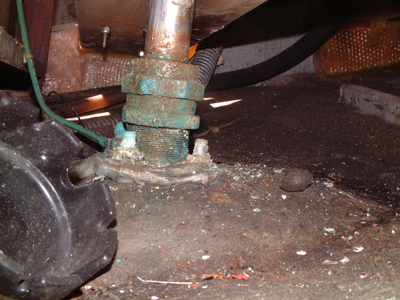
| Over that winter I started planning how I could get at the stuffing box to either tighten or re-pack it. The solution arrived in the person of my wee welsh friend, Martin. Martin could fit down into the lockers in a way I never will and at least he could see the stuffing box. He confirmed that it was indeed leaking and that there were ample threads on the fitting to allow it to be tightened significantly. So we probably didn't have to re-pack it at this time. | |
 Moisture on the Rudder Post Stuffing Box |
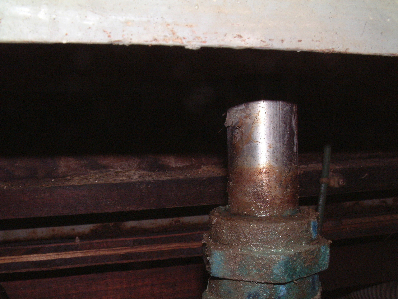
About this time I was able to get my digital camera down into the area of the stuffing box and took the pictures above, and on the left. In the top picture you can see the amount of thread below the lock nut (bottom nut). The picture on the left shows the moisture on the top of the stuffing box. This was at least one source the bilge water on Sarah. |
|
Our first problem was to find a wrench of sufficient size to work the nuts on the stuffing box. We measured the nut with a micrometer to be about 2-1/2". I have a Channel Locks adjustable wrench that is large enough. However that type of wrench would be difficult if not impossible to use on the nut. Through one of the service shops at the marina I acquired a large pipe wrench, shown in the picture on the right. |
 Large Pipe Wrench for the Stuffing Box |
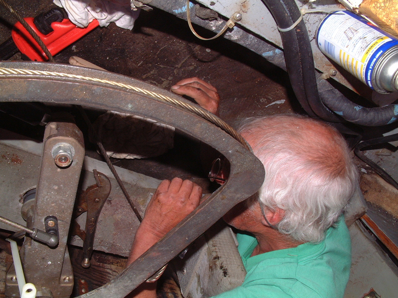 Martin Squeezing Around the Steering Quadrant |
Even with that wrench and Martin's small size it was still not possible to effectively work on the stuffing box. We finally removed the port side pulley for the steering cable and Martin could squeeze in between the rudder stop and the generator battery box to get the wrench on the nuts with some leverage. |
|
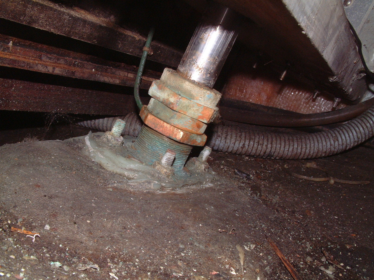
The
result is the picture on the right. The stuffing box has been tightened up
about one full turn and fitting cleaned up with a wire brush. As of now
there is no detectable leak through the rudder stuffing box. If it starts to leak again it will finally be time to repack the fitting. Hopefully that is a year or two off. |
 Tightened Rudder Post Stuffing Box |
|
Before departing Lagos, PT in the spring of 2007 I had the Sopromar Yard attempt to re-pack this stuffing box (it had begun a slight leak after the Med Cruise in 2006). They also had great difficulty in getting close enough to the gland to effectively clean out the old packing material. They removed as much as they could then put in as much fresh packing as would fit. |
|
| More Rudder Post Issues | |
|
At the end of April, 2010 I received an email from Jack Tyler as he and
Particia on Whoosh were enroute to the Marquesa Islands. He had
noticed significant vibration in the cockpit and concerned that a rudder
failure was possible he climbed into one of the cockpit lockers to
investigate. It turned out the vibration was not due to a rudder
problem, but he did discover another issue. There is a plastic bushing
on the rudder post that apparently is a bearing surface for the post where
it goes through a wooden brace, just above the stuffing box. This
bushing had ridden up the post and was clear of the wooden brace. This
situation allowed the rudder post to move a bit. Jack pushed the
bushing down into the wood and secured it with a hose clamp. |
|
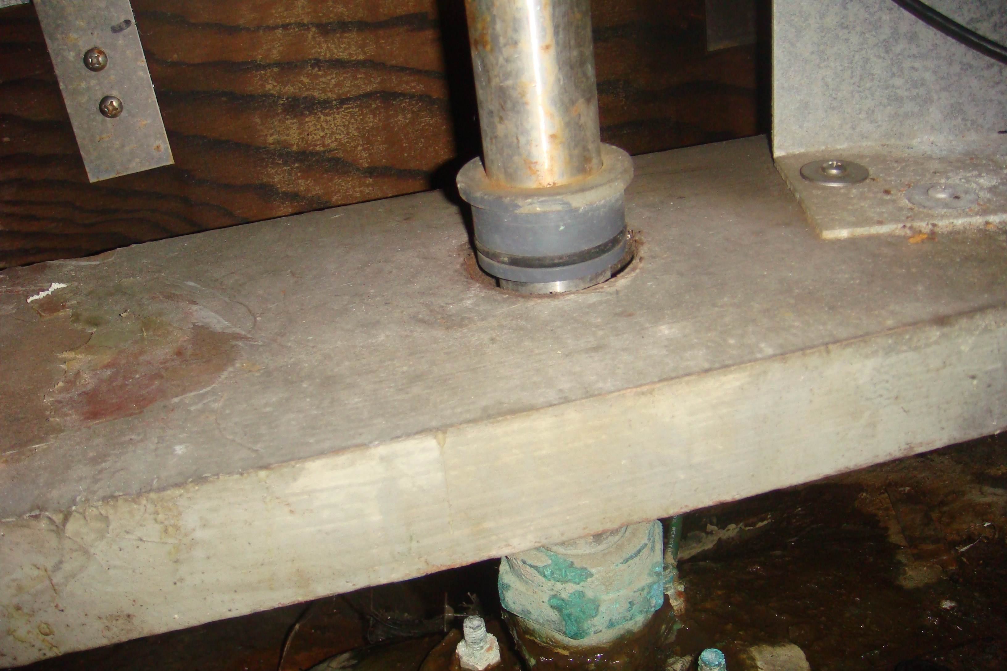 Rudder Post Bushing Out of Place |
When
I received this email I stuck my head down the lazarette locker in Sarah's
cockpit and discovered I have the same issue. From the lazarette I could not reach the bushing with enough leveage to push it down into the brace. This situation may be the source of the periodically loose stuffing box. The slight movement of the rudder post allowed by this bushing being out of place may have contributed to the stuffing box issue. |
| Later that year, while Sarah was in the Deaton's Yacht Services yard in Oriental, NC, I had one of their munchkins push the bushing back in place. | |