Sailing Vessel (SV) Sarah
Sarah has a new owner as of 7/26/2021. There will be no more updates to these SV Sarah pages
Sarah has a new owner as of 7/26/2021. There will be no more updates to these SV Sarah pages
| Rebuilding the Engine Box and Cover | |
Contents:
|
|
| The Original Engine Box | |
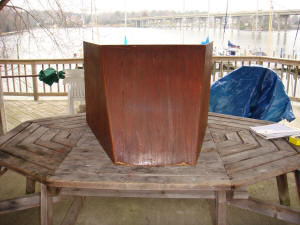 . .Original Pearson 424 Engine Box |
After Sarah's Repower was complete, my next big project related to the engine was to rebuild the original engine box and cover, shown on the left |
| The box always was a problem. The sides were built in one piece and is therefore very awkward to handle whenever I needed full access to the engine compartment. There was really only one place to put it and that was on top of the aft cabin berth (where I sleep). I usually kept a piece of drop cloth on top of the cover when it was in place. I used this cover to protect the bed sheets from being soiled by the cover. It was really not an effective solution. |
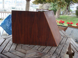 Side View of the Original Engine Box |
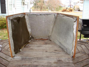 Inside of Original Engine Box |
The
other problem with original engine box is the lack of sound
proofing. I don't know what kind of stuff Pearson used on the
inside of the box, but it is very thin and not very effective. Of course if Pearson had put substantial sound proofing inside the box it would likely have been too heavy lift. |
| The final problem is the new engine installation. As show in the picture on the right, the water hoses betwee the heat exchanger and the mixing elbow are routed to an anti-siphon valve mounted above the engine. The hoses extend outside of the limits of the box. So I can't put the box back on Sarah even if I wanted to. |
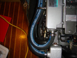 Engine Water Hoses After Re-Power |
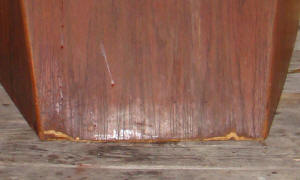 Wear and Tear on the Engine Box |
If
all of the problems described above were not enough, the box is
showing definite signs of wear and tear. It is time to replace
the box for that reason alone. However, in re-building the engine box I need to solve all of the problems and limitations of the existing one. |
|
2. It must be fully sound proofed. This is another reason for a break apart design. With 1" of sound proofing each of the sides of the box will weigh over 10 lbs. 3. The box dimensions must be modified to accommodate the engine water hoses. 4. The edges of the box components must be reinforced to minimize damage when being removed or re-installed. |
|
|
On
the right are a few of the fittings I intended to use to hold the box
together and in place.
Ultimately I did not use these fittings to secure the box in place (see
below). I planned to use the break apart hinges (top of photo) to secure the sides of the box to the bulkheads on either side of the engine compartment. They would act as pintles and gudgeons to hold the sides vertical. Holddown Clamps, such as the one at the bottom of the photo were planned to secure the box sides to the front. I also planned to use a pair of these clamps to secure the box cover. With the original box the cover just sat on top of the box with nothing but its weight to keep it from flying loose. I think I will ultimately use the hold-down clamps to secure the top, but I did not used them on the box sides, nor did I use the hinges. I still think the hinges are a good way to attach the sides to the bulkheads outboard of the engine compartment, but they are not necessary and I had enough to do on this project. I did use the hinges on a later storage project. |
|
| I thought it would be easy to design a new box using FastCAD on
my computer. First I would take the measurements from the
existing box and create a drawing of the box in FastCAD. Then
I would modify the drawing to accommodate the new dimensions and the
separate sides of the box. From that drawing I could create
templates for each piece of the new box. Apparently I over-estimated my skill as a mechanical drawer. I wanted to draw the new box in 3D, but I couldn't get it to work so I went back to working in 2D. |
|
| Fixing Bulkhead Above the Engine | |
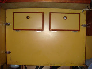 Removable Bulkhead Above the Engine |
Before
I really get into designing the new engine box I needed to take care
of some old issues with the removeable bulkhead above the engine compartment.
This bulkhead was secured by four wood screws into cleat stock on the side bulkheads. That would be fine if this bulkhead rarely, if ever has to be removed. However there is a great deal of wiring behind this bulkhead. It is the best route for wiring between the starboard and port sides of the boat. Therefore anytime I have work on electrical or instrument cabling I generally have to get behind this bulkhead at least once. Also, to gain access to the aft end of the engine this bulkhead must be removed. |
| Over the years of removing and replacing the wood screws that hold the bulkhead in place I've had to increase the size of those screws at least twice as the holes in the cleat stock get worn down. With the engine box out of the boat for an extended period of time this was the ideal time to come up with another way to secure the bulkhead other than with wood screws. | |
|
I elected to go with barrel bolts such as the one in the picture on
the right. This is a Perko barrel bolt so you know it was
expensive ($35, I think). However the Perko fitting was the
only one I could find that included a bulkhead keeper and a friction
pad to hold the bolt in place and eliminate rattle. Not only
do I not want to listen to the rattle of these bolts when underway,
but I also don't want them working their way open. The bulkhead keeper is a plastic insert for the hole in which the barrel slides. The friction pad is another piece of plastic under the base of the fitting. This presses against the barrel bolt to hold it in place. |
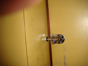 Barrel Bolt to Secure the Bulkhead |
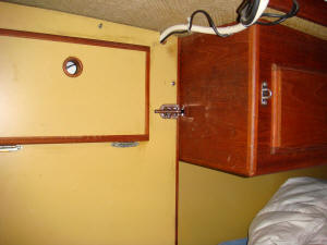 Single Barrel Bolt on the Port Side of the Bulkhead |
There
are two barrel bolts on the starboard side of the bulkhead,
replacing the two wood screws. On the port side, shown in the picture on the left, I could fix only one barrel bolt. The bottom corner of the bulkhead on this side is not fixed in place. I'm not sure this will be important and the new engine box cover should press against the lower portion of the bulkhead and keep it from moving or rattling. |
|
If this is not the case I will likely fit a hold-down clamp, such as
the ones I had planned to use on the engine box, to secure this corner of the
bulkhead from the side. With the Yanmar repower I have an additional need to periodically get behind this bulkhead. Unlike the Westerbecke, the Yanmar engine uses a overflow reservoir for coolant. This is where you check the coolant level and add coolant when necessary. |
|
|
The only effective location for this reservoir was behind the
bulkhead as shown in the picture on the right. With the engine box in place I can check the coolant level by removing the engine box cover, but I can't add coolant with the bulkhead in place. So, one more reason to make the bulkhead easier to remove and replace. |
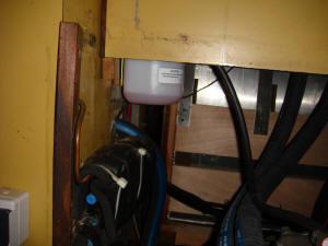 Coolant Overflow Reservoir |
| Designing the New Box | |
| Although building an engine box would not be a difficult task for an accomplished Boatwright, that is one skill for which I make no claim. I'll just have to muddle through this as best I can with a lot of time spent designing the new box and testing my approach. I'll also seek as much advice as I can from those with more skill and experience than I. | |
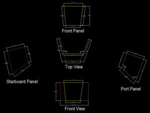 CAD Drawing of New Engine Box |
My first task was to generate a CAD drawing of the old box so I
could dispose of it. From that I created a drawing of the new box, which is expanded on the starboard side to accommodate the water hoses going to the anti-siphon valve above the engine. The image on the left is a JPEG rendering of the CAD drawing. The drawing in Autocad DWG format can be downloaded from here. |
| I cut a couple of pieces of scrap wood to the dimensions of the base of the new box and laid them on the cabin sole to verify the dimensions. These test wood strips are shown in the picture on the right and below. |
Determining the Dimensions of the Base of the Box |
|
Starboard Side of Engine Compartment |
The
picture on the left shows to test strip for the starboard side
panel of the box. It angles more outboard than the panel on
the original box, which was nearly symmetrical. The new box
will not be symmetrical. The test strip shows that the dimension of this panel will allow at least 1" of acoustical foam to be applied to the inside of the panel without coming into contact with the hoses. |
| The
side panels will be vertical, perpendicular to the cabin sole.
The front panel must be angled aft to fit under the companionway
ladder. The base of the front panel must fit between the
ladder leg holders and the aft edge of the cabin sole, as shown in
the picture on the left. This picture also shows the asymmetrical nature of the new box, with the front panel extending several inches further to the starboard side than to the port side. |
Front of Engine Compartment |
|
Port Side of Engine Compartment |
The port panel may be the most difficult to get right. The aft half of this panel does not rest on the cabin sole. It must fit flush with the triangular piece of teak that is fastened to the cabin sole next to the aft bunk. This may have been a screw up at Pearson when the cabin sole was cut for the engine compartment, or the cabin sole may have been damaged during a previous ownership and the damaged portion cut-away, then covered. |
| Since the original box was a single piece, the lack of support under a portion of this panel was not a problem. With my new design, each of the panels will disconnect from the others, so I must provide additional support for this panel. I thought the break apart hinges shown above would do this job, but this is a very tight space. When I decided fitting the hinges in this tight spot would be more difficult than it was worth, I just added some support under the panel (see below). | |
| The Mock-Up | |
| The
first real step in determining if my design was valid and to
finalize the dimensions was to build a mock-up of the engine box. I had been pretty much idle on the engine box project for several months since I completed a preliminary design and a CAD drawing. In late July I started to work with Ken Spring at the Small Open Boat Shop (SOBs) in Port Republic, MD, about 15 miles from Solomons. |
|
| Ken and his shop will do the mill work and provide consultation on
the construction of the box. I'll do the grunt work of fitting
the box and building the mock-up from which the final product will
be created. On the left is the three-sided mockup in place. |
Engine Box Mockup |
|
Starboard Side of the Mockup From Above |
The
mockup is made from a combination of Luan plywood (front piece) and
a cardboard/wood fiber panel. (side pieces). The pieces are
held together with duct tape (what else?). On the left is the starboard side of the mock-up as seen from above. It shows the clearance that will be provided for the engine water hoses. I will also have plenty of room to add sound deadening material. |
| This is a similar view of the port side of the box, which is not significantly changed from the original box. |
Port Side of the Mockup |
|
Inside Front of the Mockup |
The inside of the front panel showing engine clearance. |
| The base of the front panel. The fittings on the cabin sole are the bases for the companionway ladder. |
Outside Front of the Mockup |
|
Mockup With the Ladder in Place |
The mock-up with the companionway ladder in place on the left. This shows the asymmetrical nature of the new box. The starboard side of the box has been displaced outboard to provide additional space for the engine water hoses. |
One of the first things Ken had convinced me to change was the method of securing the side panels to the front. He felt it was an unnecessary complication to use clamps for this purpose and he wasn't sure it would be secure enough. By the time I delivered the mockup and the CAD drawing to Ken I had come around to his view. Further it does not appear the hinges will be necessary to secure the aft end of the side panels as the vertical guides used in the original box should work for the new box. |
|
| First Fitting | |
|
10
Days later Ken brought down the side panels for an initial fitting -
to see if the mockup and the CAD drawings I had produced were close
to the finished product. The side panels are made from 1/2" MDO (Medium Density Output) plywood with ash edge trim. |
The Initial Fitting of the Engine Box |
|
Gettting the Fitting Correct |
Not surprisingly, the fit was far from perfect. However it was fairly close. |
| Most
of the errors appear to be in my CAD drawing. It was very
difficult to get all of the angles and joints precisely measured. In any case, Ken was not greatly disappointed that the fit was not perfect. He made additional measurements to adjust the dimensions of the panels and returned to his workshop. |
The Aft End of the Starboard Panel Requires Some Modification |
| Final Fitting | |
|
Final Fitting of the Engine Box |
Ken
returned twice more to fit and adjust the panels. On the
second fitting he made a template of the cover. Since we
weren't totally sure how the vertical panels would come out, we
delayed starting on the top until we had a reasonable fit on the
sides. During the third fitting we were both satisfied that the side panels were good. On August 13, 2008 Ken returned for the fourth and final time with the finished top and the engine box is complete, if unfinished and unfastened. |
| On the right
is a view of the port side forward corner of the box. Ken used
ash to provide the corner re-enforcement. I will initially use
wood screws to secure this corner. Ultimately I plan to put threaded inserts in the corner re-enforcement and secure the panels with machine screws. This should provide the necessary rigidity while still allowing the box to be easily disassembled. |
Port Side of Engine Box |
| The ability to take the box apart and stack the flat panels out of the
way (other than on my bunk) was one of the design goals and it
appears we have achieved that goal. I will put a small stop bock under the edge of the cabin sole at the aft end of the port panel. During one of the previous ownerships the cabin sole was carved away in this area and there is no support the aft end of the panel. This wasn't that noticeable with the previous, one-piece engine box, but is necessary to get the port panel in its proper place before securing the corner. |
|
|
Starboard Side of the Engine Box |
On the starboard side there is now sufficient room to 1" sound proofing material to the inside of the panel. |
| The full engine box with cover in place. |
Completed Engine Box |
|
And
with the companionway ladder in place.
|
|
| Finishing the Box | |
| The first thing I needed to do was fit stops and guides to properly position the two side panels. I put a vertical guide on the aft bulkhead to hold the aft edge of the starboard panel in place. |
Guide for the Starboard Panel |
|
Attempting to Provide More Support for the Port Panel |
And
a horizontal stop on the port side where the cabin sole had been
torn away by a Previous Owner (PO). First I attempted to provide more support for the port panel. |
| I also used a quarter round molding to act as a guide for the port side panel. This locks it in place so the other panel can be installed against this fixed position. |
Guide For the Port Panel |
|
Painting and Varnishing the Panels |
I painted the main part of the panel with semi-gloss white acrylic latex paint. I finished the trim on the panel with a light stain and varnish. |
|
I
put several coats of paint and varnish on the panels, then realized
the additional fitting would probably require a touch up. So I
went ahead with the final installation knowing I'll have to put
several more coats of paint and varnish on each panel. I think my ultimate solution for the top of the engine box is to cover it with rubber-like surface. I normally store toolboxes and other containers on this surface and they will mar any covering I might put on the top. |
Painted and Varnished Engine Box |
|
Panels Secured with Screws |
For the time being the panels are held together by two self-tapping screws on the leading edge of each of the side panels. I plan to use threaded inserts and screws with hand knobs for the final assembly. |
| In the picture on the right the self-tapping screw has been replaced by a fluted knob with a 1"x10-24 stud. The stud connects to a SS threaded insert in the edge trim of the front panel. The 1" stud is barely long enough to engage the inserts by more than a few threads. So I will recess the knob into the side panel by 1/4" using a 1" Forstner bit. |
Panel Secured with Fluted Knob |
|
My original holes for the lower fasteners do not engage enough of the front panel edge trim to support the threaded inserts. I will have to move those holes further up the leading edge of the side panels and fill the original holes with wood putty. The fitting and adjusting just doesn't seem to want to ever end. |
|
| Sound Proofing | |
|
I
chose to go with the sound proofing tiles offered by
Sailor's
Solutions. It seemed like an easier way to go than having
to manipulate, cut and trim a single large roll of the material. As it turned out it was pretty easy. |
|
|
Sound Proofing Tiles |
On the left I have laid 6 tiles on the underside of the top of the
box to determine how I will trim the tiles. The tiles cut
fairly easily with a long razor knife, but I did go through 4 blades
to finish the project. Sailor's Solutions states that the adhesive on the back of the tiles is very "aggressive", and I would have to agree. As long as you just lightly touch the tile to the surface you can pull it off to re-position, but once the glue grabs it will have to be scrapped off. |
| Sailor's Solution also states that you don't need to use seam tape with the tiles, but I chose to use the tape anyway. On the right is the inside of the port panel in place. |
Sound Proofing on Inside of the Port Panel |
|
Sound Proofing on Inside of Starboard Panel |
And this is the starboard panel. With the box closed the sound reduction is not that great, but I didn't expect it to be. I still have some small sections of the panels that are not covered with the sound proofing material, but a big problem is that the whole aft end of the engine compartment is open to the area under the cockpit and the cockpit lockers. I will have to cover those areas with the tiles before I achieve any meaningful reduction in the engine sound in the cabin or cockpit. |
|
The ultimate problem is the V-Drive. Since the power comes off
the forward end of the engine it is impossible to seal off the
engine compartment from the bilge area. So, no matter what I
do about the aft end of the engine compartment, engine noise will
always escape into the area under the cabin sole. For now I have declared the engine box complete and I'm on to the other projects that must be completed before I can leave this fall (2008) on another cruise. There is till work to do on this box, but it is time to go sailing. |
|
| Adding Latches | |
|
Using thumb screws to secure the sides of the
engine box to the front never really worked. It could have
worked well, but I never got the screws to line up correctly with
the threaded inserts. So I've been looking for another way to keep the box together when underway. In May 2012 I was ordering some hardware from the McMaster-Carr online catalogue and noticed they have a large selection of stainless steel draw latches. I wasn't sure how this might work on the engine box, so I ordered two different types of latches. |
Draw Latches on the Engine Box |
|
Close-Up of the Draw Latch |
I ordered a set of corner-mount compression spring latches, thinking
that would be the solution. I also ordered a pair of their
versatile-mount latches that included a variety of strikes. Turns out I could not make the corner mount latches work, but the versatile-mount latches seem to work very well. As shown in the picture above I mounted one latch on each side of the box and the two strikes on the front (photo on the left). The latches draw the sides and the front tightly together. |
| I think I will add a couple of more latches to hold the top to the sides and front, but for now the weight of the top should keep it in place. I wanted to secure the latches with 1/8" Fast Pins, but the smallest I could find was 3/16". So I've used Hitch Pins instead. These are from Lowes and are not stainless, but I don't think that will matter much for this application. | |