Sailing Topics
| NMEA 183 Troubleshooting with the Windows HYPERterminal |
| The HYPERterminal software disappeared from the standard Windows software with Win7, and NMEA 183 networks are rapidly disappearing from most cruising sailboats. So a discussion of using one of these obsolete products to troubleshoot the other is clearly not that useful anymore. I've left this page on the website as a historical artifact for anyone researching the early days of marine electronics. Also there might still be someone out there with 10 year old electronics (such as I) and an old WinXp machine tucked away somewhere on board (again someone like me), for whom this page might be very up-to-date. |
| When a vessel is configured for electronic navigation with a GPS
and chart plotter there must be a way to connect the GPS (and other
instruments) to the chart plotter. There are a number of ways
to do this, but the most common are to use a single vendors
proprietary networks (e.g., Raymarine SeaTalk, Furuno NavNet, etc.)
or use the industry standard NMEA 183 connection. If you use a
proprietary network the installation is usually very straightforward
as the manufacturer has designed and tested the configuration
installed on your vessel. However, that implementation is
limited to the devices from a single manufacturer, which is not
always desirable. The NMEA 183 protocol was designed to provide
for interoperability between devices from different manufacturers,
which eliminates the limitation of a proprietary protocol.
However the use of NMEA means the specific devices and network
configuration you are implementing on your vessel likely have not
been tested by any of the manufacturers involved. To one
extent or another you are on your own when troubleshooting the
configuration. The most common problem encountered is when
everything is connected and powered up - nothing happens. The
GPS seems to be sending data, but the chart plotter doesn't appear
to be receiving the data. Clearly there is an interfacing
problem, but is it in the GPS setup, the chart plotter setup, or
cabling between the two? If the chart plotter is a dedicated device such as a Raymarine C-series Multi-Function Display (MFD) there is usually a buffer display feature that can be used to determine is data is being received. Then it is generally a matter of checking and tweaking the interface settings on the GPS and plotter, re-seating or replacing the interface cable until data is going from the GPS to the plotter. If the chart plotter is a software package running on a Wintel PC you have an additional interface to trouble shoot - that is the interface between the plotting software and the Windows OS. I find it very useful to first determine that data is being received on the PC communications port before starting to troubleshoot the plotting software. The principal tool I use to determine that the PC is receiving data is the HYPERterminal software provided as an accessory with the Windows OS. |
 The
value of the HYPERterminal is that it is a simple piece of software
that emulates a communications terminal on the PC. It can be
used to display data received on any COM port configured on the PC. The
value of the HYPERterminal is that it is a simple piece of software
that emulates a communications terminal on the PC. It can be
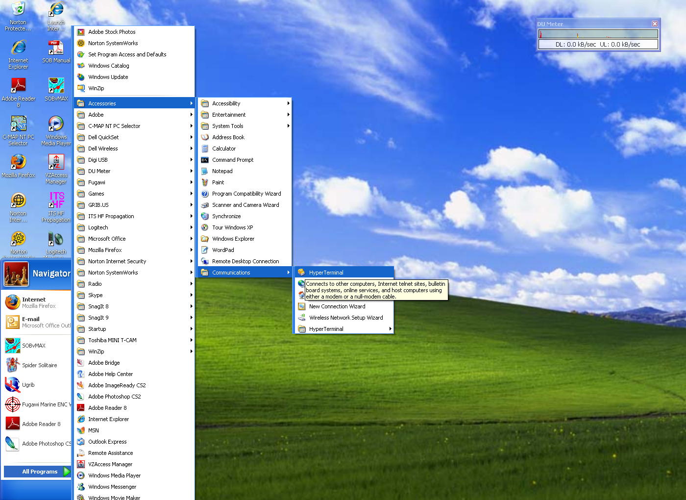
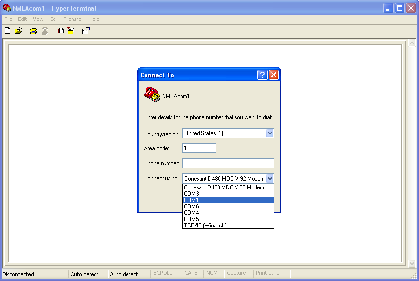
used to display data received on any COM port configured on the PC.In the screen capture on the left I am starting the HYPERterminal program, which is located in the Accessories folder under Communications. |
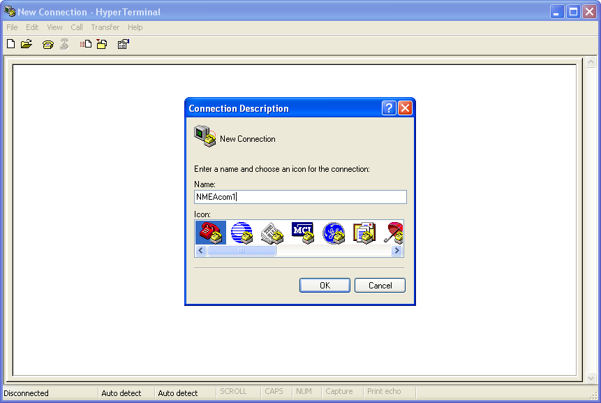
 When
the HYPERterminal program is first started it must be configured and
this configuration given a name. On the right I am creating a
new configuration and naming it, "NMEAcom6". COM port 6
happens to be the port on my navigation computer that is used for
input from the NMEA network. When
the HYPERterminal program is first started it must be configured and
this configuration given a name. On the right I am creating a
new configuration and naming it, "NMEAcom6". COM port 6
happens to be the port on my navigation computer that is used for
input from the NMEA network. |
 The
next configuration parameter is to specify the computer port to be
used. I have selected COM6, which is my NMEA port. I am
using COM6 because my NMEA network is connected to a USB port.
On many computers the NMEA cable is connected to the hardware COM
port, which is normally COM1. The
next configuration parameter is to specify the computer port to be
used. I have selected COM6, which is my NMEA port. I am
using COM6 because my NMEA network is connected to a USB port.
On many computers the NMEA cable is connected to the hardware COM
port, which is normally COM1. |
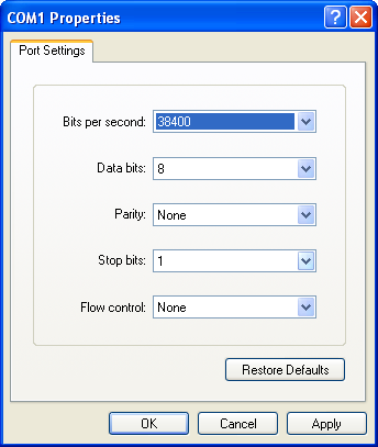
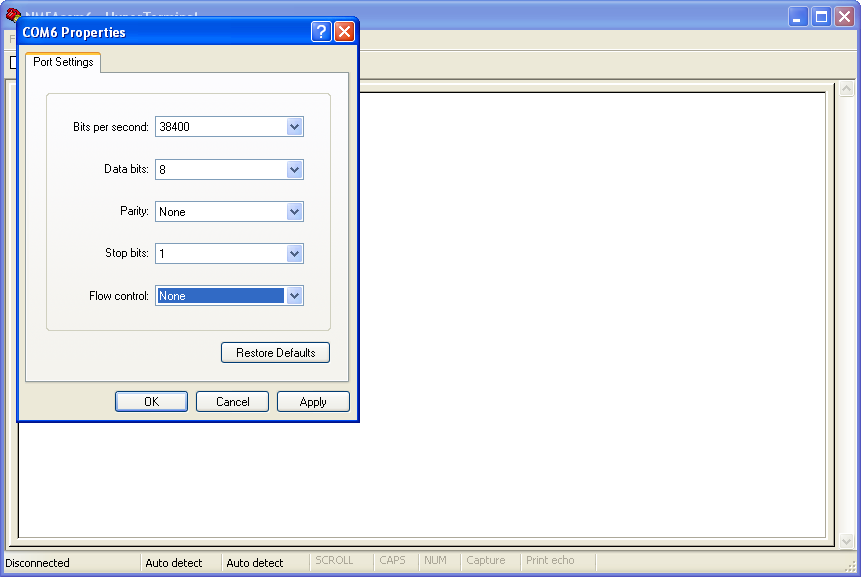 When
a COM port is specified it then must be configured. In the
screen capture on the right I have configured the program for COM6
on my computer. When
a COM port is specified it then must be configured. In the
screen capture on the right I have configured the program for COM6
on my computer.Normally the NMEA 183 data rate (top parameter) is 4800 bits per second or Baud. However, my NMEA network includes AIS data, which should run at 38400 Baud. The remaining parameters are standard for a NMEA 183 network, no matter the Baud rate. |
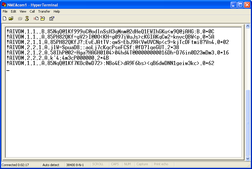
 When
I clicked OK on the configuration above, the HYPERterminal program
connected to COM6 and immediately started to receive NMEA data. When
I clicked OK on the configuration above, the HYPERterminal program
connected to COM6 and immediately started to receive NMEA data.If I were having problems with my chart plotting software I would at least at this point know that the NMEA data was coming into the computer. |
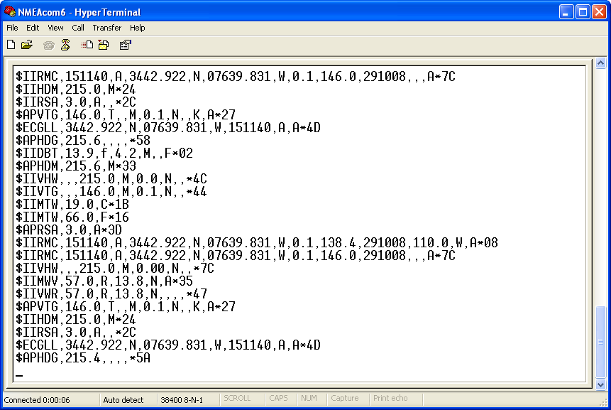
 I
could also use the HYPERterminal display to look for specific
sentences in the NMEA data stream. The screen capture on the
right is the same as that above, but I have added notations to
identify some of the sentences. I
could also use the HYPERterminal display to look for specific
sentences in the NMEA data stream. The screen capture on the
right is the same as that above, but I have added notations to
identify some of the sentences. |
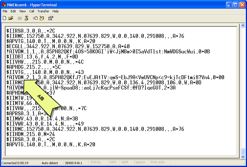 In
this screen capture I have flagged one of the AIS sentences
received. In
this screen capture I have flagged one of the AIS sentences
received.So if this were a real troubleshooting scenario I would know that the PC is receiving good NMEA data, I would also be able to determine if a specific sentence was being received and what values are in the sentence. If the input data looks good, then I know the problem is not with the sending device (e.g.; GPS) or the network cabling. I would then concentrate on the setup for the chart plotting software to isolate and correct the problem. In order to validate the contents of a given NMEA sentence you will need documentation on the sentences, which is sold by the NMEA at an exorbitant charge. However you can find the structure for the most common sentences here. |
| The HYPERterminal can also be used to troubleshoot a NMEA network when a dedicated chart plotter is configured, however it is not as effective in that configuration. Most likely the dedicated chart plotter has a different cable termination for the network than that on a PC. So the cabling must be changed to connect the network to the PC. The results of the HYPERterminal testing is this case would not be as definitive as for a PC-based plotting program and the cabling changes could also introduce a problem that doesn't exist in the operational network configuration. However the HYPERterminal can still be used to verify that the transmitting device (e.g., GPS, AIS, etc.) is actually sending data. |
| Trouble Shooting an AIS Receiver with the HYPERterminal. |
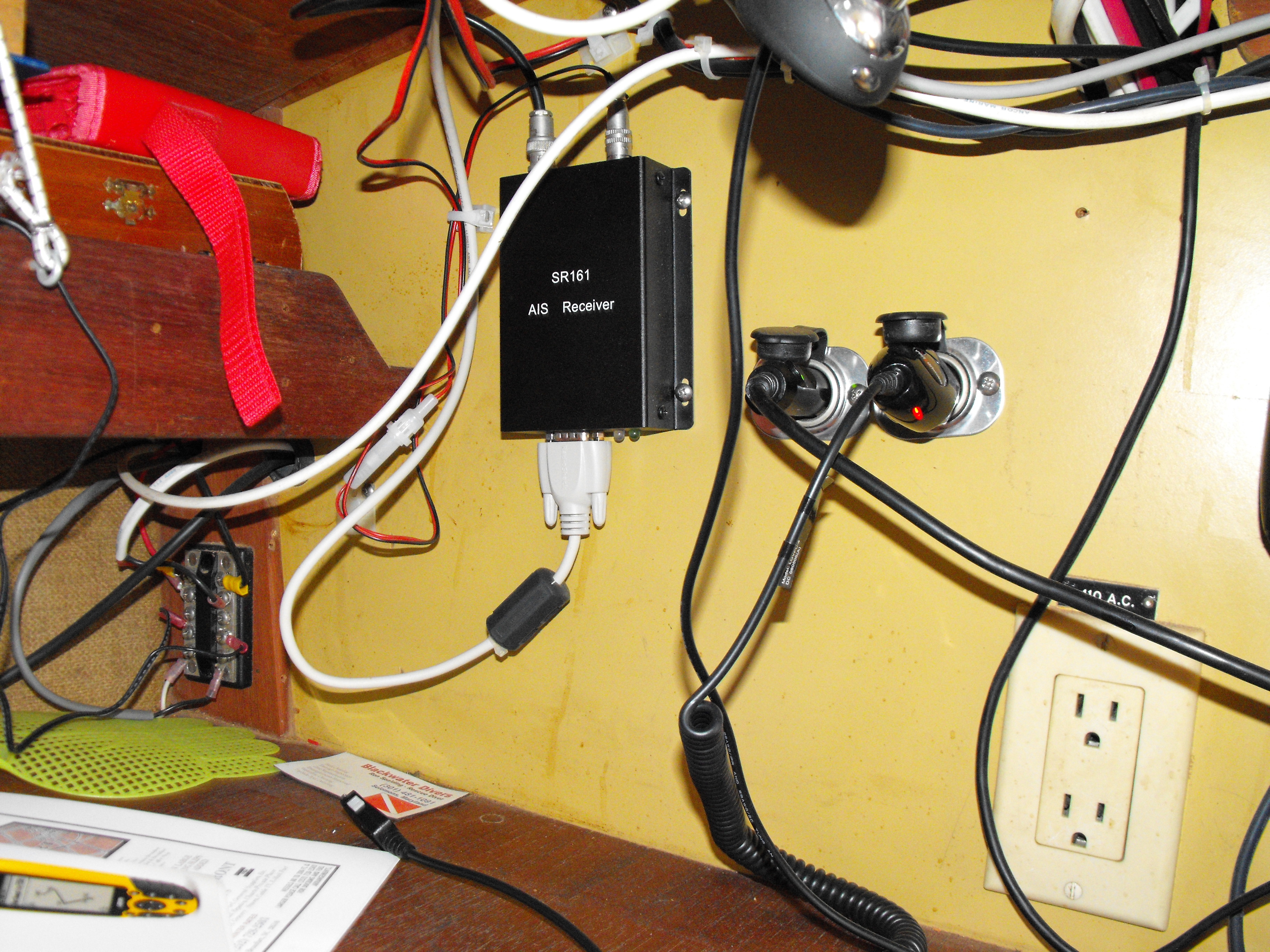 I
initially installed a NASA AIS Engine on Sarah in early 2006.
I subsequently replaced the NASA AIS Engine with the SR161 AIS
Receiver from Miltech. The SR161 is shown in the picture on
the right. I
initially installed a NASA AIS Engine on Sarah in early 2006.
I subsequently replaced the NASA AIS Engine with the SR161 AIS
Receiver from Miltech. The SR161 is shown in the picture on
the right.Both of these devices are very simple dedicated VHF radio receivers. There is very little diagnostic capability in either unit, but at least the SR161 does have LED lights to indicated AIS traffic is being received. The NASA unit does not provide even that limited amount of information. I have published several pages on the installation and operation of these AIS receivers on Sarah, which can be found in the SV Sarah section using the link at the tope of this page. |
One of the difficulties with troubleshooting an AIS installation
is that the receiver only sends data to the NMEA network when a good
ship transmission has been received. Most yachts are berthed
far from the shipping channels so there is not a lot of data
available for troubleshooting. Even if you can look out of the
cabin and see a commercial vessel you can't be sure it is equipped
with an AIS transponder and if it is the transponder is operational.
That was true in 2007 when I first posted this section of the page.
Today the proliferation of class B AIS transponders on yachts, and
the tendency of yacht owners to keep their transponders broadcaster
even when berthed, means there is almost always an active AIS
transponder in range. However a stationary class B transponder
sends the dynamic data packet only once ever 3 minutes, alternating
the channel with each transmission. With a single channel
receiver such as my SR161 I will receive that message only once
every 6 minutes. So even now (2019) I have to wait a long time
for an AIS message to show up. The rest of this discussion
pertains to the situation I was dealing with in 2007.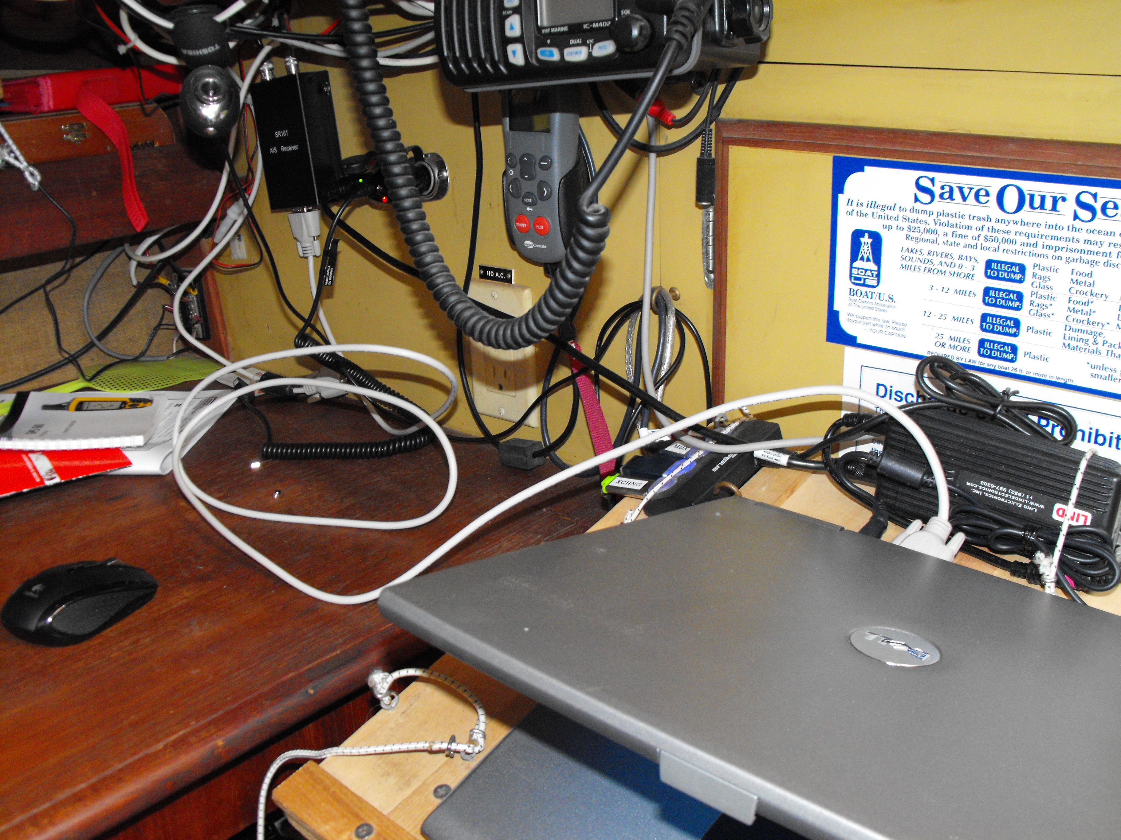 So
if you've completed or modified the installation of an AIS receiver,
but are not seeing any data on your plotter you don't have any idea
whether or not there is a problem. So
if you've completed or modified the installation of an AIS receiver,
but are not seeing any data on your plotter you don't have any idea
whether or not there is a problem.For me the easiest way to troubleshoot either of these AIS receivers is to connect it to a COM port on my PC and use the HYPERterminal as a diagnostic tool. In the first picture, above, the SR161 is connected directly to my Brookhouse NMEA Multiplexer, which combines the AIS data with that from my Raymarine devices into a single data stream to both my PC and the Raymarine C-120 MFD. I don't want all that other data on the HYPERterminal if I'm troubleshooting the AIS receiver, so in the picture on the right I have disconnected the SR161 from the Brookhouse Mux and I have used a spare RS232 cable to connect the SR161 directly to the COM port on my PC. |
 I
have named this HYPERterminal configuation NMEAcom1; I
have named this HYPERterminal configuation NMEAcom1; |
 because
I am using the COM1 port. because
I am using the COM1 port. |
 The
port settings are the same as for COM6. The
port settings are the same as for COM6. |
 In
this case I have a working configuration and Sarah is berthed near a
number of large motor yachts who have AIS transponders. So as
soon as I clicked OK on the Port Settings I immediately started
receiving AIS traffic from the SR161. In
this case I have a working configuration and Sarah is berthed near a
number of large motor yachts who have AIS transponders. So as
soon as I clicked OK on the Port Settings I immediately started
receiving AIS traffic from the SR161.If I were having a problem receiving AIS data on my chart plotting software this validation of the SR161 operation would tell me to start looking at the NMEA Mux connections and the setup in the plotting software as the source of the problem. Clearly the AIS receiver is working and sending data. But what would I do if this screen remained blank? I still wouldn't have any evidence of a problem. Here is where a common feature of both the NASA AIS Engine and the Miltech SR161 is handy. Both allow a GPS to be connected to the data cable (RS232) between the AIS receiver and the NMEA network. The receivers act as multiplexers combining the GPS data with the AIS data sent to the chart plotter. |
| Using a GPS to Troubleshoot the AIS Receiver Connection |
 In
order to use this multiplexer feature of the AIS receiver you first
must connect a GPS to the AIS data cable. NASA provides a
cable with the AIS Engine specifically for this purpose. The
terminal at the AIS Engine end of the cable has a small blue wire.
This wire is connected to the Data Out (DO) pin on the GPS.
The Signal Ground (SG) pin on the GPS is connected to the same
negative battery terminal as the AIS Engine. In
order to use this multiplexer feature of the AIS receiver you first
must connect a GPS to the AIS data cable. NASA provides a
cable with the AIS Engine specifically for this purpose. The
terminal at the AIS Engine end of the cable has a small blue wire.
This wire is connected to the Data Out (DO) pin on the GPS.
The Signal Ground (SG) pin on the GPS is connected to the same
negative battery terminal as the AIS Engine. The SR161 has the same capability, but Miltech sells the necessary cable separately. Fortunately for me, Miltech uses the same pins on the data cable as NASA, so the NASA cable also works with the SR161. Wiring the GPS to the AIS cable is not a difficult thing, but it is not something I would do just to trouble shoot the AIS receiver. Rather it is a very useful feature providing a backup path for a GPS to the chart plotter and something I implemented for its own sake. On Sarah I have installed a deck plug under the dodger which connects the DO pin to the AIS Engine data cable. |
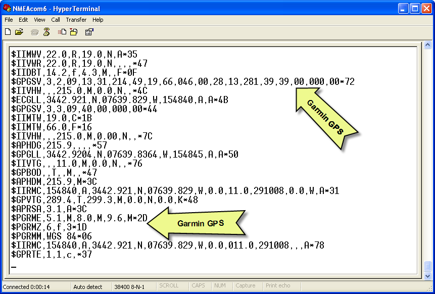 Having
already wired the GPS to the AIS data cable, I now have a useful
tool to validate the connection between the AIS receiver and my
chart plotter. In the screen capture on the right I have
annotated a few of the NMEA sentences from the Garmin handheld GPS
that have been received on the HYPERterminal from the SR161. Having
already wired the GPS to the AIS data cable, I now have a useful
tool to validate the connection between the AIS receiver and my
chart plotter. In the screen capture on the right I have
annotated a few of the NMEA sentences from the Garmin handheld GPS
that have been received on the HYPERterminal from the SR161.If I had done some modifications to my NMEA network, the chart plotter or the SR161 I can use the GPS to verify the connection between the SR161 and my chart plotter without having to wait for a ship to come within range. Of course this doesn't prove the SR161 can receive AIS transmissions, but it does give me confidence that if the SR161 does receive an AIS transmission it will successfully send it to the chart plotter. |