Sarah's Atlantic Circle
| European Shore Power Plan | |||||||||||||||||||||||||||||||||||||||||||||||||||||||||||||||||||||||||||||||||||||||||||||||||||||||||||||||||||||||||||||||||||||||||||||||||
| This page documents my planning and implementation of the electrical modifications to Sarah for European 230VAC/50Hz mains power. Much of this planning was done in conjunction with Jack & Patricia Tyler's modifications to their Pearson 424, Whoosh. Jack & Patricia completed their modifications in 2003 and cruised in Europe from 2003-2008. Their modifications and experience with European power are documented on Whoosh's page on European power options also published on this web. | |||||||||||||||||||||||||||||||||||||||||||||||||||||||||||||||||||||||||||||||||||||||||||||||||||||||||||||||||||||||||||||||||||||||||||||||||
| Sarah's onboard electrical wiring was
established for 115VAC. Most of the electrical devices on board were
designed for 110-120VAC and 60hz power. In Europe the mains power available
will normally 220-240VAC and 50hz. I am not going to replace all onboard
electrical equipment when I get to Europe, nor will I do this again when I
return to the States after the Atlantic Circle cruise. Therefore I need to
modify the existing wiring to accommodate European mains power while most of
the boat remains internally wired for U.S. mains power. The basic component required to accommodate European power is a power isolation transformer. This will step down the voltage to 115, but does not change the frequency. Electrical devices that require 60Hz power either must not be used, be replaced or have their power supplied by an inverter. Some devices are capable of operating with 115VAC 50Hz power (e.g., air conditioner, refrigeration), but they will run slightly slower and less efficiently than on 60Hz power. The estimated live-on-board AC power requirements for the boat are summarized by the table below.
|
|||||||||||||||||||||||||||||||||||||||||||||||||||||||||||||||||||||||||||||||||||||||||||||||||||||||||||||||||||||||||||||||||||||||||||||||||
| The purpose of the table above is identify which loads would be supplied by the isolation transformer (shore) and which would be supplied by an inverter. Subsequently I decided to not install an inverter, so all of the power requirements in the table (60 KW) must be supplied by the transformer. That load is mitigated somewhat by the replacement of some equipment (e.g., space heater) in Europe. Those devices run off a 230VAC circuit not on the transformer. As I spend time in Europe the number of such devices will undoubtedly increase. | |||||||||||||||||||||||||||||||||||||||||||||||||||||||||||||||||||||||||||||||||||||||||||||||||||||||||||||||||||||||||||||||||||||||||||||||||
|
While in Europe I will have three options to provide power for these requirements:
At departure i had only one group of onboard equipment that could be powered by the first option. That equipment is my computer and peripherals. This group can be powered by any of the four options. However it is also prudent to allow for the purchase of small appliances in Europe (e.g., space heater, coffee maker, etc.). While in Europe I will have no option except to buy 230VAC 50Hz appliances. The third option is only practical for periods when shore power is not available such as at anchor. Because the generator is noisy and uses up diesel fuel at a minimum rate even when no loads are active, the generator will be only for critical or emergency use. I had hoped to provide a great deal of my AC needs via an inverter, even when shore power is available. An inverter would allow me to provide 60 Hz power so long as the battery charger could keep up with the load on the batteries. However I would not want heavy, resistive loads such as the water heater and space heaters to be powered from the inverter. This meant I would have to do a major replacement of the onboard AC wiring to allow two sources of power to the AC panel - transformer power and inverter power. In the end I accepted that this solution would be too complicated, time consuming to implement and it can be somewhat risky to have two AC power sources in the same panel. |
|||||||||||||||||||||||||||||||||||||||||||||||||||||||||||||||||||||||||||||||||||||||||||||||||||||||||||||||||||||||||||||||||||||||||||||||||
| Installing the Isolation Transformer | |||||||||||||||||||||||||||||||||||||||||||||||||||||||||||||||||||||||||||||||||||||||||||||||||||||||||||||||||||||||||||||||||||||||||||||||||
 Mastervolt IVET-D Isolation Transformer |
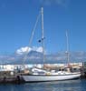
So in the end I have gone with the straight forward solution of putting a 3.5 KVA power transformer inline with the shore power between the deck receptacle and the distribution panel. For this purpose I purchased a Mastervolt IVET-D 16/3.5 MT (picture on the left). The IVET-D input is selectable between 230VAC and 115VAC via a switch inside the cabinet. The output can be either 230VAC or 115VAC depending on which power taps are used for the output wiring. The MT stands for Multi-Tap. | ||||||||||||||||||||||||||||||||||||||||||||||||||||||||||||||||||||||||||||||||||||||||||||||||||||||||||||||||||||||||||||||||||||||||||||||||
|
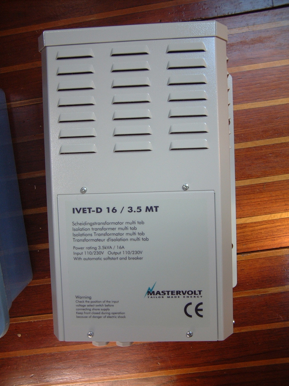
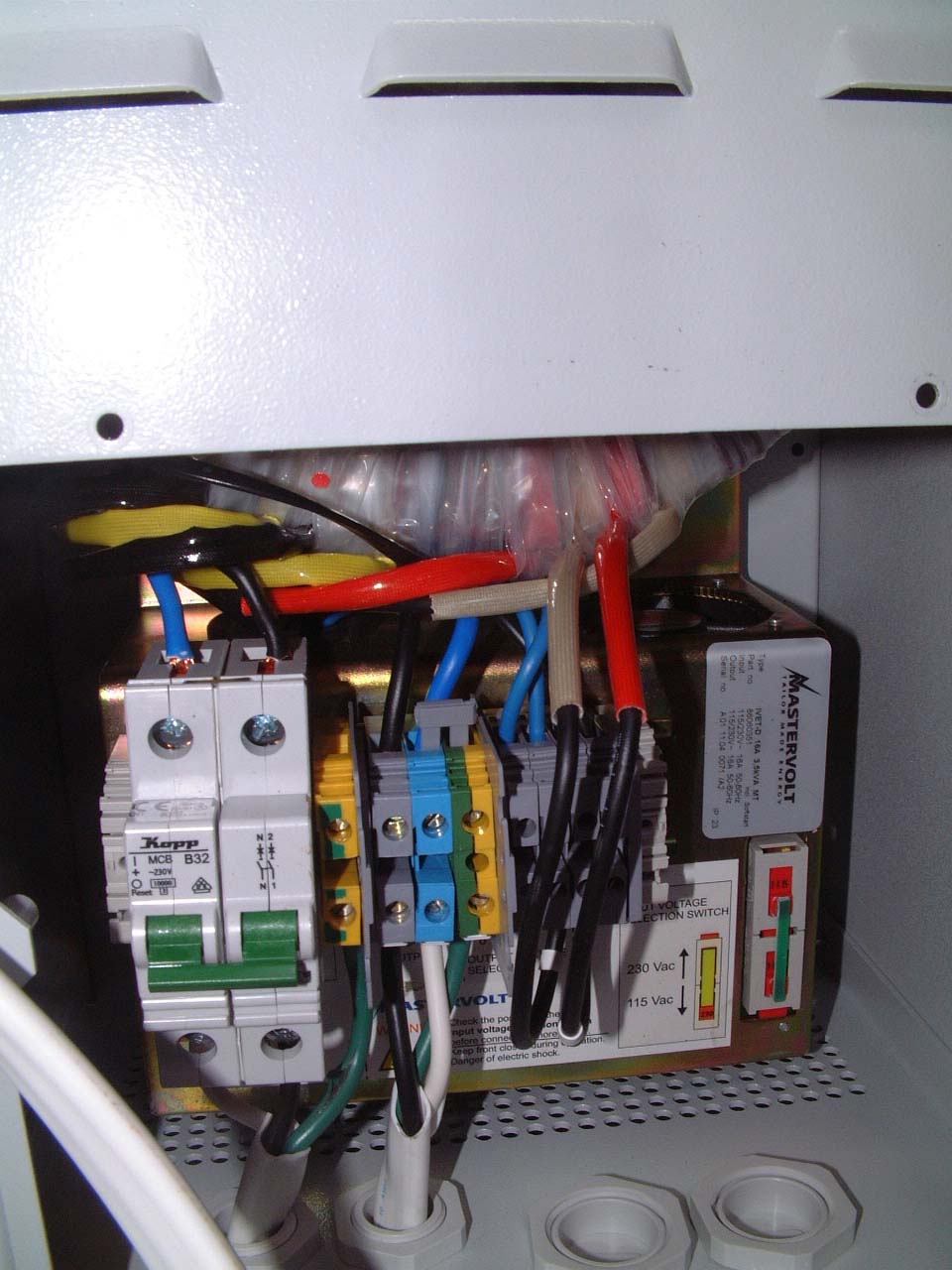
Therefore my current onboard wiring will receive power from the 115VAC taps. Initially the input power will be set to 115VAC as well. When I arrived in the port of Horta I changed the switch setting from 115VAC to 230VAC. I also swapped out the internal circuit breaker for the transformer. The unit came with a 16 Amp breaker for European power. Prior to installation I replaced that breaker with a 30 Amp breaker supplied with the unit (bottom picture on the right). This allowed me to use the full 115VAC 30 Amp service the boat has been wired for. With 230VAC power in European, 30 Amps would represent a very dangerous overload situation hence the need for the 16 Amp breaker. |
 Wiring Conncecctions and Circuit Breaker |
||||||||||||||||||||||||||||||||||||||||||||||||||||||||||||||||||||||||||||||||||||||||||||||||||||||||||||||||||||||||||||||||||||||||||||||||
| I still plan to purchase and install a high capacity inverter for those times when shore power is not available and I wish to avoid the noise and fuel consumption of running either the generator or the main engine. | |||||||||||||||||||||||||||||||||||||||||||||||||||||||||||||||||||||||||||||||||||||||||||||||||||||||||||||||||||||||||||||||||||||||||||||||||
|
|
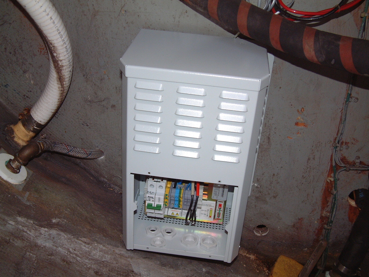
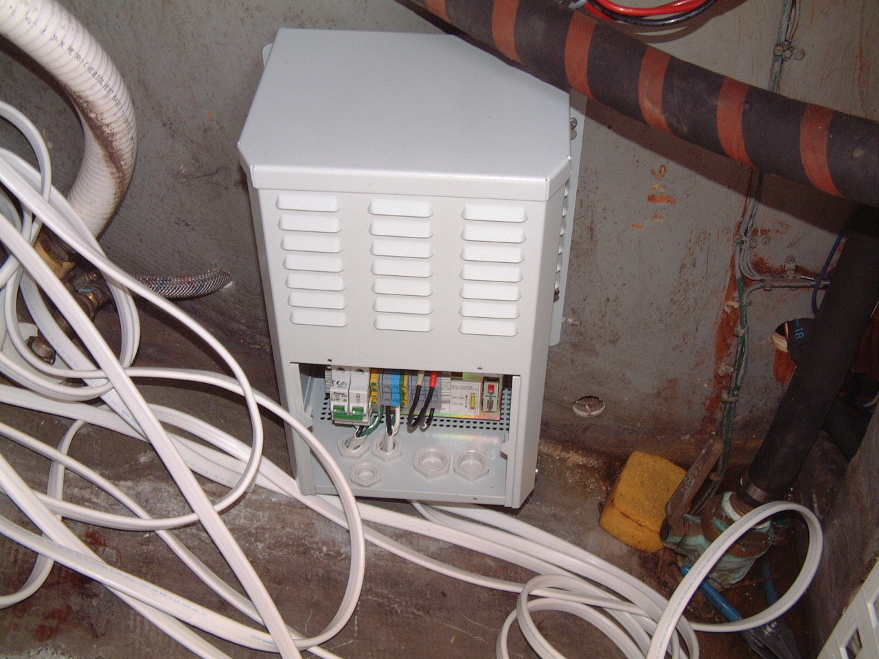
After much procrastination I finally mounted the transformer in the port cockpit locker, just below the battery charger. At the time this picture was taken I had not begun to perform the wiring (hence the wiring cover has been removed). I will need to run a new shore power cable from the deck receptacle to the transformer. Then I will run a new service cable from the output of the transformer to the power source selector switch in the aft cabin. This switch selects either shore power or the generator as the onboard power source. Currently this switch resides on the main power panel above the navigation station. I would like to move it below the the navigation desk in the space left when I removed the old battery selector switch. | ||||||||||||||||||||||||||||||||||||||||||||||||||||||||||||||||||||||||||||||||||||||||||||||||||||||||||||||||||||||||||||||||||||||||||||||||
|
One of the feature of the Mastervolt IVET-D transformer that turned out to be a problem is the internal circuit breaker. This breaker must be replaced when switching between 230 VAC and 120 VAC. Because I mounted the unit so low in the locker replacing the breaker was very difficult. Eventually I added a separate breaker for the tranformer above the unit on the bulkhead. This made switching the breaker much easier. I will also steal Jack Tyler's idea of taping off the input circuit (see 230VAC Circuit, below). While here in the states this will be a non-functional circuit, but once in Europe is will provide a means for me to bring 230VAC power on board for European appliances (e.g., space heaters, coffee makers, etc.). |
|||||||||||||||||||||||||||||||||||||||||||||||||||||||||||||||||||||||||||||||||||||||||||||||||||||||||||||||||||||||||||||||||||||||||||||||||
| Well, once I began to wire up the transformer I discovered that I had mounted the cabinet just a little too low on the bulkhead. I kept it low primarily to minimize how high I had lift the 23 kg while fastening it to the bulkhead. I also had to stay under the fuel fill hose (brown and black) and other wiring that was secured to the bulkhead. I left enough room to get the wire in through the glands on the bottom (no knockouts on the side), but it would have been difficult if not impossible to secure the gland in place once the wiring was complete. I considered doing nothing with the glands and started to secure the input cable ends in the appropriate terminals. |
 First Wiring Attempt |
||||||||||||||||||||||||||||||||||||||||||||||||||||||||||||||||||||||||||||||||||||||||||||||||||||||||||||||||||||||||||||||||||||||||||||||||
| I had difficulty getting the ground wire into its terminal (yellow/green terminal next to the breaker). I could see the wire entry only with a small mirror and then not at all when my hand was in the way guiding the wire into the terminal. Eventually I loosen the terminal screw too much and the clamp came loose. There was no way I could put the terminal back together while cramped down in the cockpit locker. | |||||||||||||||||||||||||||||||||||||||||||||||||||||||||||||||||||||||||||||||||||||||||||||||||||||||||||||||||||||||||||||||||||||||||||||||||
 Wires In the Glands at the Bottom of the Transformer |
So I took the transformer off the bulkhead and out of the locker. It was fairly simple to put the terminal back together once I could see what I was doing and wasn't laying on my side in the locker. Since I now had full access to the cable glands, and I didn't want to have to remount the transformer more than once, I went ahead and attached the input and output wires and secured them with the glands. Then I got a second chance at a hernia hoisting the transformer up on the bulkhead while trying to put the bolts through the bulkhead. At last the transformer was back in place with wiring ready to be run. That would be another day's task. | ||||||||||||||||||||||||||||||||||||||||||||||||||||||||||||||||||||||||||||||||||||||||||||||||||||||||||||||||||||||||||||||||||||||||||||||||
| Finally the isolation transformer installation is complete (in the picture the cables still need to be secured). I routed the input power cable back to the existing shore power receptacle and the output cable to the power panel above the navigation station. I disconnected the shore power at the deck receptacle, then verified the shore power connection at the power selector switch. I disconnected the existing power cable at the switch and the receptacle and connected up the cables to and from the isolation transformer. Next I switched on the breaker in the transformer and closed up the cabinet. |
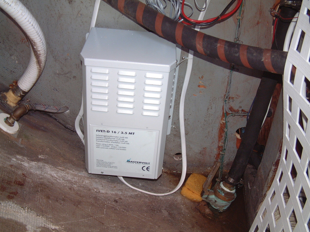 Transformer Installation Complete |
||||||||||||||||||||||||||||||||||||||||||||||||||||||||||||||||||||||||||||||||||||||||||||||||||||||||||||||||||||||||||||||||||||||||||||||||
|
Then with the main breaker at the panel off I
connected up the shore power. With all individual breakers off I turned on
the main breaker and observed 115VAC on the meter. Next I checked the
polarity at the panel and it was correct. One by one I turned on the
individual circuits to see if there were any anomalies, and there were
none. So now I can re-fill the port side cockpit locker. This job is essentially done. I still haven't decided what kind of an inverter I will install. I think I'll put off that decision until after I have been cruising for few months. I did purchase a small (500 W) inverter that can be plugged into a cigarette lighter type receptacle. I will use that inverter to charge the various batteries for many on board devices (cameras, drills, flashlights, computers, etc.). I still need to remove the old AC wiring and the old AC breaker box, but that will probably wait until next winter. That will involve a lot of opening of wiring harnesses and I don't have time for it now. |
|||||||||||||||||||||||||||||||||||||||||||||||||||||||||||||||||||||||||||||||||||||||||||||||||||||||||||||||||||||||||||||||||||||||||||||||||
| 230VAC Circuit | |
|
Well,
nearly a year after installing the transformer I finally got around to
installing a separate 230VAC circuit on Sarah. This circuit will provide
power for whatever European appliances I might purchase on the Atlantic
Circle cruise. At this time (Jan, 2006) I have been in European waters for
a little over 6 months, but all onboard electrical equipment is still
limited to the devices I brought with me from North America. I'm not sure
how much longer my two-year old space heater will last in the marine
environment, nor am I sure if next winter a single space heater will
suffice. I had planned to install this circuit before I left Florida, but I
ran out of time. Actually I had plenty of time, I just hate doing
electrical work on Sarah. The only thing I hate worse than electrical work
is plumbing. So it was easy to keep putting off this task until it was
absolutely necessary. As yet the need is not absolute, but I need to do a lot of re-wiring anyway, so the time will never be better. |
|
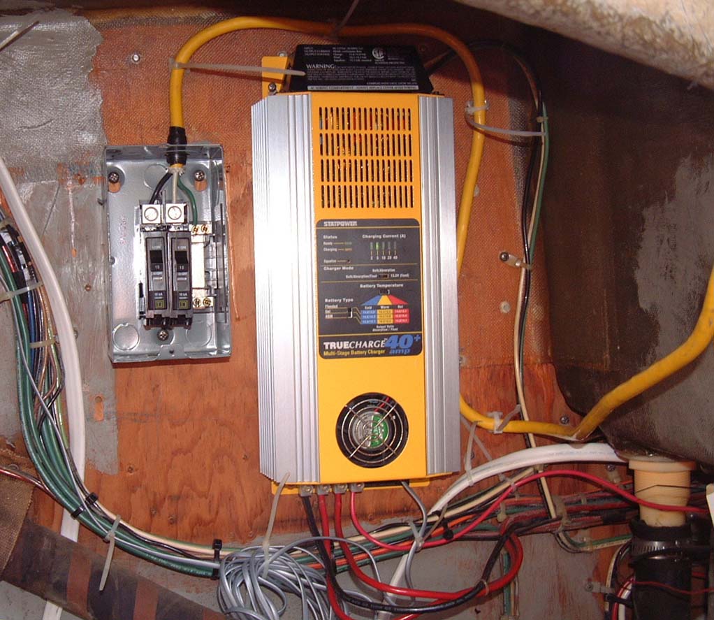 Breaker for Non-Isolated 230 VAC Power |
On the left is a picture of the 10A dual breaker box I have installed above the transformer, next to the battery charger. I put one breaker on each leg of the circuit. This is a Square D power box, purchased before I left the U.S. It, and the breakers, are rated for 90-250VAC 50/60Hz. Once I complete running the electrical cable through the cabin to an outlet box, I'll pick up the power from input to the transformer. |
|
On the right I have installed a 230VAC outlet in the aft cabin, near the Navigation Station. For now this will be the only 240VAC outlet on Sarah. As you can see I have purchased a European space heater, which can now be used. I haven't really needed a second heater. The 115VAC heater I brought from the states is still working fine and provides all the heat I have needed over this winter in Cascais. However, that heater has been onboard Sarah for nearly 3 years. That's about the life expectancy of household appliances in a marine environment. If that heater fails, my only option will be the 230VAC heater. Hence the need to complete this circuit even if it doesn't get used this year. |
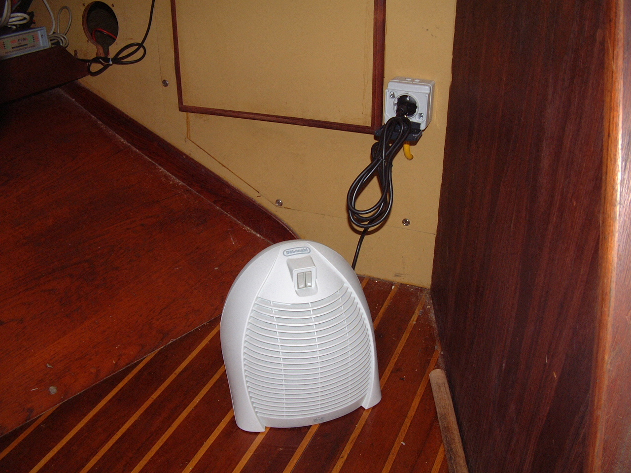 230 VAC Outlet and European Space Heater |
| My old heater did fail later that first winter in Portugal and I depended on this 230VAC heater during the following winter in Lagos, PT. | |
| Re-Installing the Isolation Transformer | |
|
The Mastervolt transformer worked flawlessly for three years in Europe.
On the way back from Europe, while stopped in Bermuda I switched the unit
from 230VAC input to 115VAC input. This involves throwing a switch to
select the input voltage and then replace the 16A breaker I had used in
Europe with a 32A breaker for U.S shore power. The breaker swapout is the
only drawback to the Mastervolt unit. Actually it is more a problem
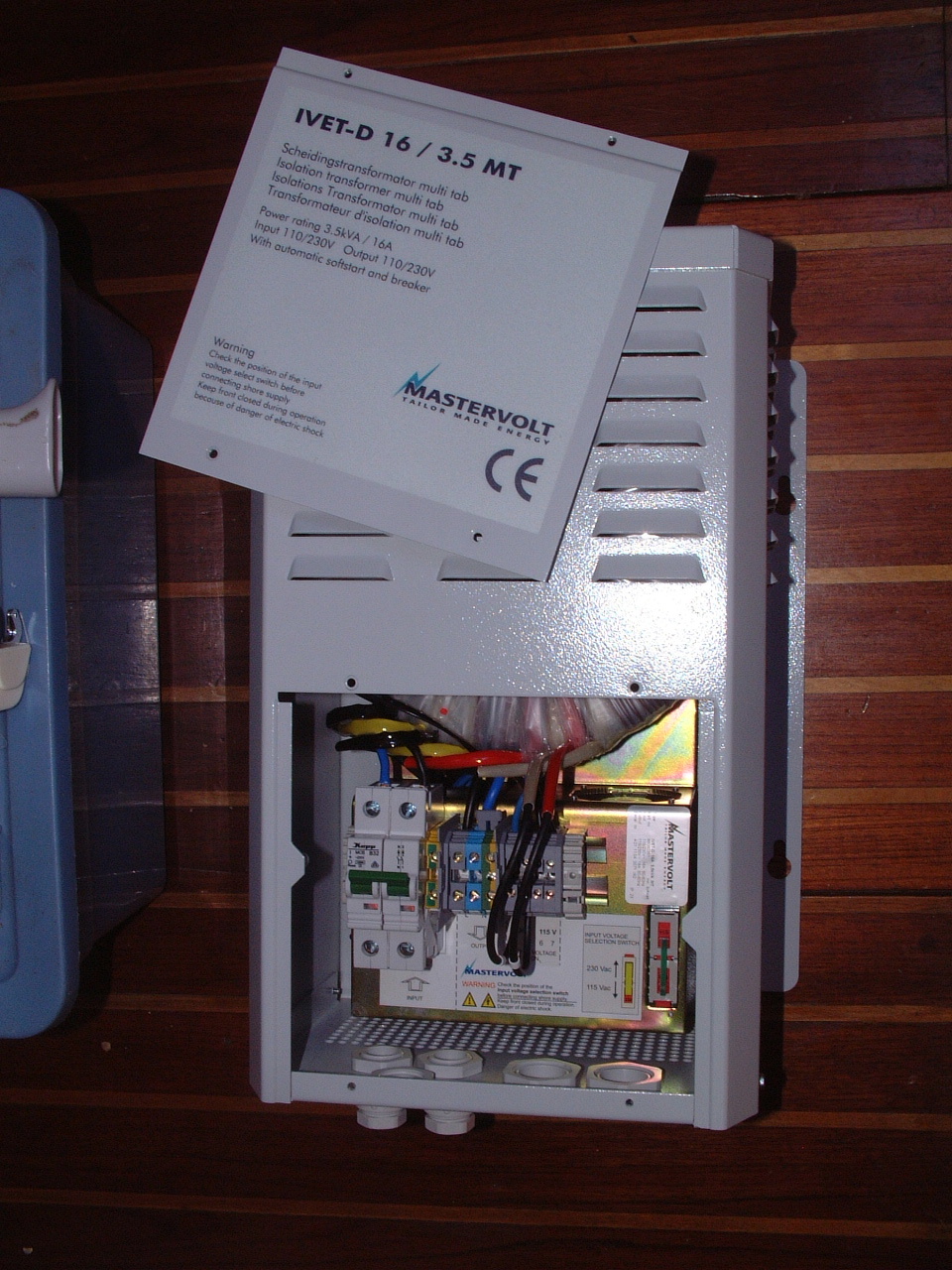
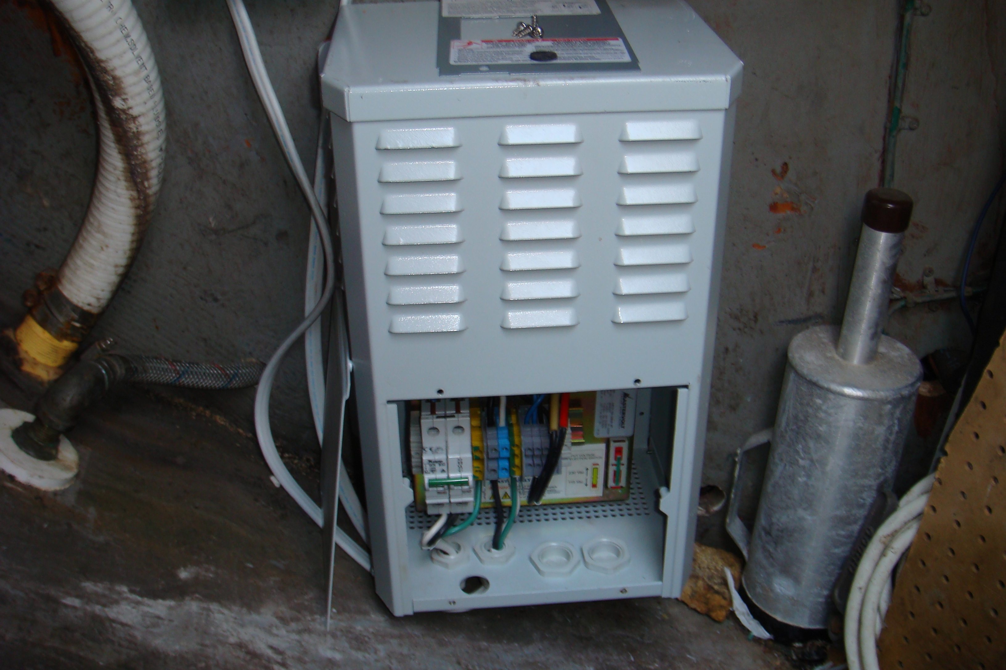
with how I located the unit. From the picture below you can see that
the unit is mounted very low in the locker. This makes it very
difficult to disconnect, replace and re-wire the breaker. I pretty
much have to do it by feel as I can't get my head very near the opening in
the transformer. Although it seemed to be working OK in Bermuda, I may not have gotten neutral wire on the load side securely attached to the breaker. Everything continued working until December, 2007 in Maryland when the weather had turned cold. I was running a space heater, water heater, frig and battery charger through the transformer. The poor connection to the neutral wire appears to have overheated burned through the wire. I was lucky there wasn't an electrical fire. The result was the loss of shore power on Sarah on a very cold December day. It took me awhile to discover the problem was the transformer. My quick fix was to just jumper the transformer out of the circuit until I could get the transformer repaired. I waited until early March, when the repower was completed, to tackle the transformer. With its weight and the awkward location on the bulkhead in the locker it was not a lot of fun getting it off the boat. I shipped it to the Mastervolt repair facility in Ft. Lauderdale, FL. The technician called me back within a week to say the unit had been repaired under warranty and he was shipping it back to me. He said the cause of the failure was the burnout of the neutral wire from input voltage switch to the primary coil. The coils were fine. |
|
 Transformer Re-Installed After Repairs |
Now I had to go through the installation all over again. I decided to
change things so that the switching of the breaker was not such a difficult
task. For this I attached short wires cables to the input and output terminals of the transformer, then re-mounted it on the bulkhead. |
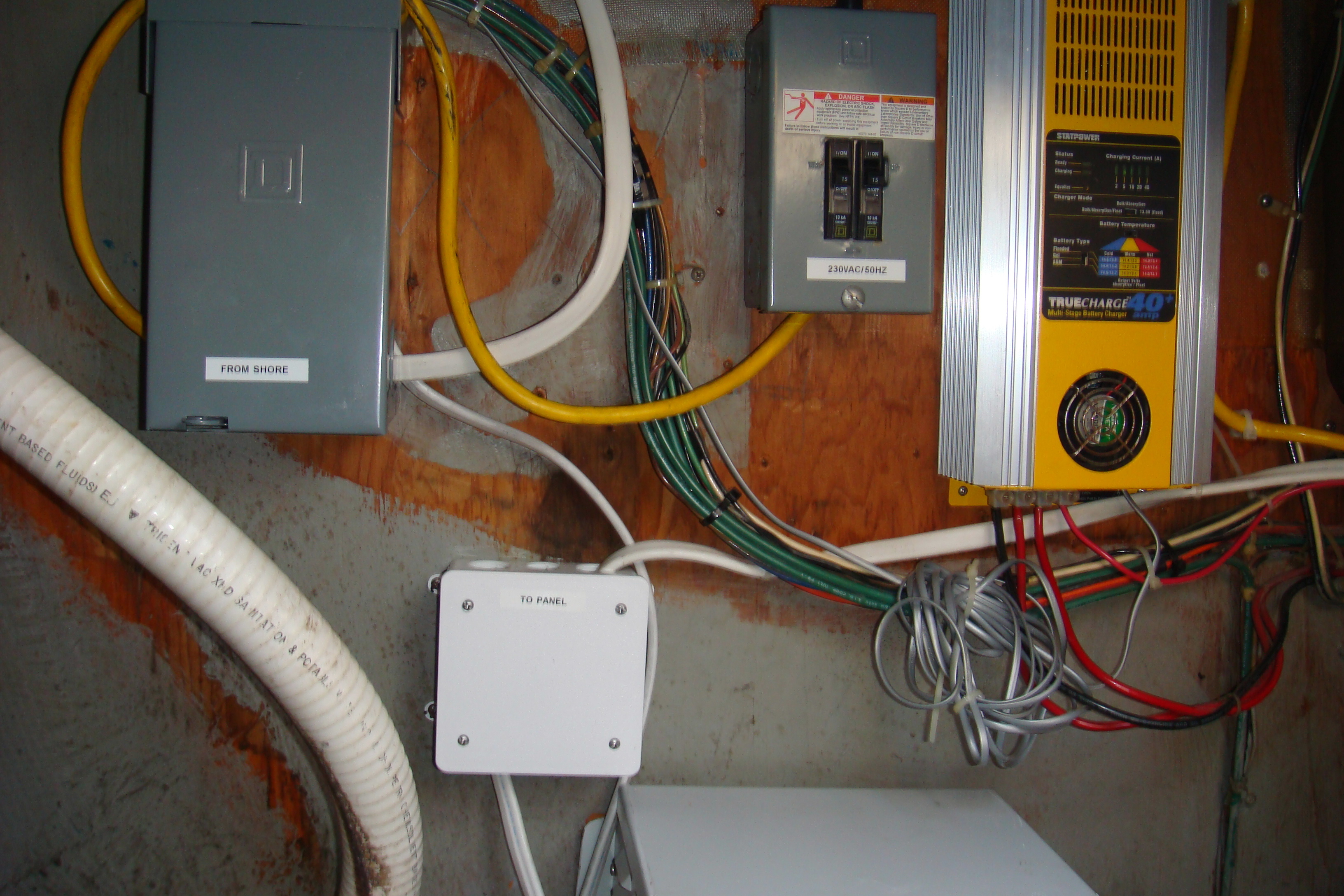
| Next I installed a SquareD breaker box above the transformer on the same bulkhead. I connected the source side of the 30A breaker in this box to the shore power receptacle and the load side of the breaker to the input cable to the Transformer. I also installed a plastic junction box on the bulkhead where I mated the output cable from the transformer to the cable going to the AC electrical panel. | |
|
The
new breaker box is in the upper left corner of the picture on the right.
This box is high enough that it is relatively easy to re-wire. This a
dual, ganged breaker. One breaker is connected to the hot wire and the
other to the neutral wire. The yellow cord is for the 230VAC50Hz outlet described above. That cable is not currently connected to the shore power. If I ever sail Sarah back to an area where the mains power is 230VAC, I will swap the 30A breaker in this box with SquareD 15A breaker and connect the 230VAC outlet cable to the source side of the breaker. That outlet has its own 10A breaker box to the right of new box. In the lower center is the junction box used to connect the output of the transformer to the on board AC panel. |
 External Circuit Breaker and Junction Box |
 Re-Installation Complete |
In the picture on the left I have closed up the electrical boxes and put
labels on each. Now when Sarah cruises to a port with 230 VAC power I will only throw the switch on the transformer for 230 VAC input. I will leave the 32 A breaker in place. Instead I will swap out the breaker in the SquareD box with a 15 A model. I will not have to make any wiring changes to the transformer, which may have been the source of the problem in 2008. |
|
If I ever have to remove the transformer for repairs or replacement I
will only have to disconnect the cables from the transformer to the breaker
box and the junction box, then run a short cable from the breaker to the
junction box to restore (non-isolated) power to the boat. Of course if the transformer fails where the mains power is 230VAC I will be SOL and will not have shore power until the transformer is repaired. The main thing is I was able to connect the cables to the transformer while it was out of the boat and on a work surface. I am confident those wire connections are secure. In addition the new breaker and junction boxes are easily accessible and those connection are also secure. |
|